Gérer les réseaux et le trafic
Dans CloudStack, les VMs invitées peuvent communiquer ensemble en utilisant les infrastructures partagées avec la sécurité et la perception que les utilisateurs ont un LAN privé. Le routeur virtuel CloudStack est le composant principal fournissant les fonctionnalités réseaux pour le trafic invité.
Trafic invité
Un réseau peut transporter le trafic invité seulement entre VMs à l’intérieur d’une zone. Les machines virtuelles de zones différentes ne peuvent pas communiquer ensemble en utilisant leurs adresses IP ; elles doivent communiquer avec les autres par le routage de leurs adresses IP publiques.
Voir une configuration typique du trafic invité ci dessous :
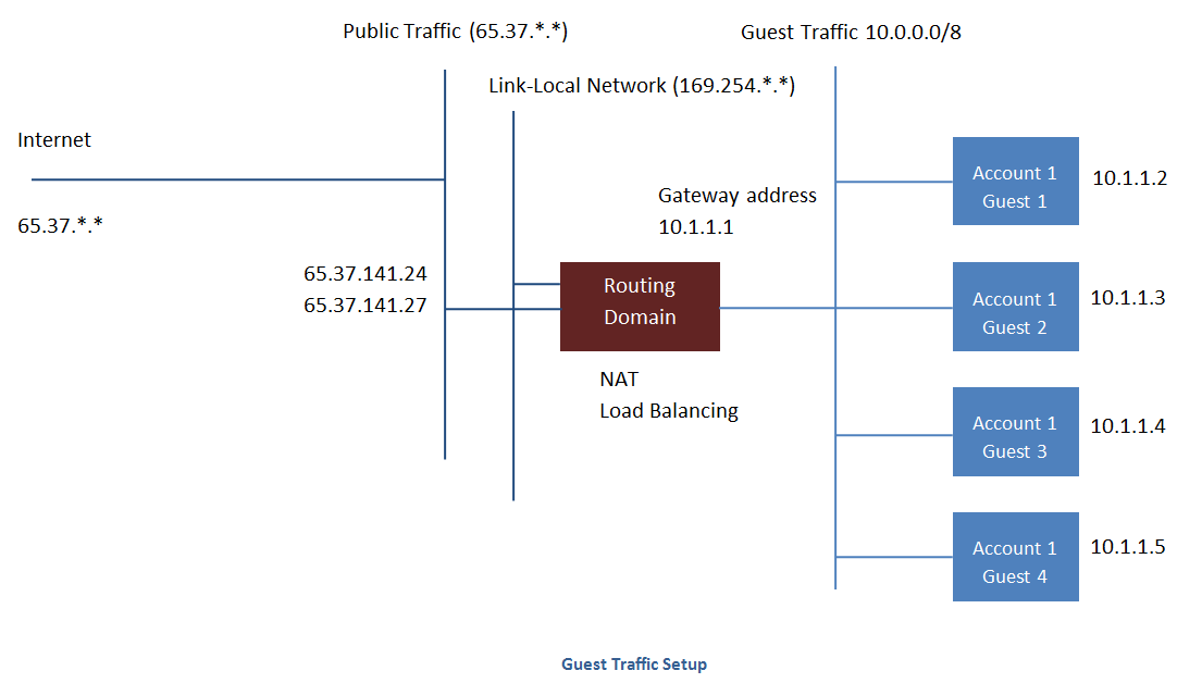
Typiquement, le serveur de gestion crée automatiquement un routeur virtuel pour chaque réseau. Un routeur virtuel est une machine virtuelle spéciale qui fonctionne sur les hôtes. Chaque routeur virtuel dans un réseau isolé à trois interfaces réseaux. Si plusieurs VLAN publics sont utilisés, le routeur aura plusieurs interfaces publiques. Son interface eth0 servira de passerelle pour le trafic invité et a comme adresse IP 10.1.1.1. Son interface eth1 est utilisée par le système pour configurer le routeur virtuel. Son interface eth2 a une adresse IP publique d’assignée pour le trafic publique. Si de multiples VLAN publics sont utilisés, le routeur aura plusieurs interfaces publiques.
Le routeur virtuel fournit le service DHCP qui va automatiquement assigner une adresse IP pour chaque VM invitée dans l’intervalle d’IP assignées au réseau. L’utilisateur peut manuellement reconfigurer les VMs invités pour adopter différentes adresses IP.
Le Source Nat est automatiquement configuré dans le routeur virtuel pour transférer le trafic sortant de toutes les VMs invitées.
Le réseau dans un Pod
L’image suivante illustre la configuration du réseau au sein d’un seul pod; Les hôtes sont connectés à un commutateur de niveau pod. Au minimum, les hôtes devraient avoir un lien montant vers chaque commutateur. Les agrégats d’interfaces réseaux sont également supportés. Le commutateur du pod est une pair de commutateurs gigabits redondants avec des liens à 10G.
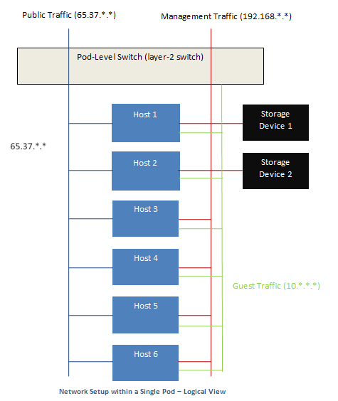
Les serveurs sont connectés comme ceci :
Les périphériques de stockages ne sont connectés qu’au réseau qui transporte le trafic de gestion.
Les hôtes sont connectés aux réseaux pour à la fois le trafic de gestion et le trafic publique.
Les hôtes sont aussi connectés à un ou plusieurs réseaux qui transportent le trafic invité.
Nous recommandons l’utilisation de plusieurs cartes physique Ethernet qui implémente chacune interface réseau comme une fabrique redondante de commutateur dans le but d’optimiser le débit et améliorer la fiabilité.
Le réseau dans une Zone
La figure suivante illustre la configuration du réseau au sein d’une seule zone.
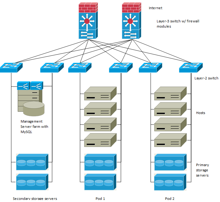
Un parefeu pour le trafic de gestion opère dans le mode NAT. Le réseau assigne typiquement des adresses IP dans l’espace d’adressage du réseau privé de classe B 192.168.0.0/16. Chaque pod se voit assigné des adresses IP dans l’espace privé de classe C 192.168.*.0/24.
Chaque zone à son propre ensemble d’adresses IP publiques. Les adresses IP publiques depuis différentes zones ne doivent pas se chevaucher.
Configuration du réseau physique d’une zone basique
Dans un réseau basique, configurer le réseau physique est assez simple. Vous devez seulement configurer un réseau invité pour transporter le trafic généré par les VMs invitées. Quand vous ajouter pour la première fois une zone à CloudStack, vous configurer le réseau invité par les écrans Ajouter une zone.
Configuration du réseau physique d’une zone basique
A l’intérieur d’une zone qui utilise le réseau avancé, vous devez dire au serveur de gestion comment le réseau physique est configuré pour transporter différents types de trafics isolés.
Configurer le trafic invité dans une Zone Avancée
Ces étapes assume que vous êtes déjà connecté dans l’interface CloudStack. Pour configurer le réseau invité de base :
Dans le menu de gauche, choisir Infrastructure. Dans Zones, cliquer sur Voir Plus, puis cliquer sur la zone à laquelle vous voulez ajouter un réseau.
Cliquer sur l’onglet Réseau.
Cliquer sur Ajouter un réseau invité.
La fenêtre Ajouter un réseau invité est affichée :
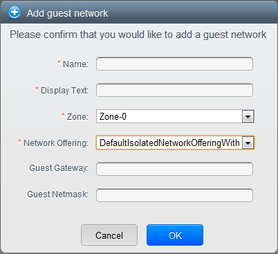
Fournir l’information suivante :
Nom : Le nom du réseau. Cela sera visible de l’utilisateur.
Texte affiché: La description du réseau. Cela sera visible de l’utilisateur.
Zone : La zone pour laquelle vous êtes en train de configurer le réseau invité.
Offre réseau : Si l’administrateur a configuré plusieurs offres de réseau, sélectionner celui que vous voulez utiliser pour ce réseau.
Passerelle invitée : La passerelle que les invités devraient utiliser.
Masque de sous réseau invité : Le masque de sous réseau utilisé sur le sous réseau que les invités vont utiliser.
Cliquez sur OK.
Configurer le trafic public dans une Zone Avancée
Dans une zone qui utilise un réseau avancé, vous devez configurer au moins une plage d’adresses IP pour le trafic Internet.
Utiliser plusieurs Réseaux d’Invités
Dans les zones qui utilisent le réseau avancé, des réseaux additionnels pour le trafic invité peuvent être ajouté à n’importe quel moment après l’installation initiale. Vous pouvez aussi personnaliser le nom de domaine associé avec le réseau en spécifiant un suffix DNS pour chaque réseau.
Les réseaux d’une VM sont définie à la création de la VM. Une VM ne peut pas ajouter ou supprimer des réseaux après qu’elle ait été créée, bien que l’utilisateur peut aller dans son inviter et supprimer l’adresse IP sur la carte réseau d’un réseau particulier.
Chaque VM a juste un réseau par défaut. La réponse du serveur DHCP du routeur virtuel configurera la passerelle par défaut de l’invité comme ça pour le réseau par défaut. Plusieurs réseaux qui ne sont pas par défaut peuvent être ajoutés à un invité en complément du seul réseau, ce qui nécessite le réseau par défaut. L’administrateur peut contrôler quels réseaux sont disponible comme réseau par défaut.
Des réseaux supplémentaire peuvent être disponible pour tous les comptes ou être assigné à un compte spécifique. Les réseaux qui sont disponibles à tous les comptes sont à l’échelle de la zone. Tout utilisateur avec un accès à la zone peut créer une VM avec un accès à ce réseau. Ces réseaux à l’échelle de la zone fournissent un peu ou pas du tout d’isolation entre les invités. Les réseaux qui sont assignés à un compte spécifique fournissent une isolation plus solide.
Ajouter un réseau invité supplémentaire
Se connecter à l’interface de CloudStack comme administrateur ou utilisateur final.
Dans la navigation à gauche, choisissez Réseau.
Cliquez sur Ajouter un réseau invité. Donnez les informations suivantes:
Nom : Le nom du réseau. Cela sera visible de l’utilisateur.
Texte affiché: La description du réseau. Cela sera visible de l’utilisateur.
Zone. Le nom de la zone à laquelle le réseau s’applique. Chaque zone est un domaine de diffusion, et par conséquent, chaque zone a une plage d’IP différente comme réseau d’invité. L’administrateur doit configurer la plage d’IP pour chaque zone.
Offre réseau : Si l’administrateur a configuré plusieurs offres de réseau, sélectionnez celle que vous voulez utiliser pour ce réseau.
Passerelle invitée : La passerelle que les invités devraient utiliser.
Masque de sous réseau invité : Le masque de sous réseau utilisé sur le sous réseau que les invités vont utiliser.
Cliquer sur Créer.
Reconfigurer les Réseaux dans les VMs
CloudStack vous offre la possibilité de déplacer des VMs d’un réseau à un autre et de reconfigurer son réseau. Vous pouvez retirer une VM d’un réseau et l’ajouter à un nouveau réseau. Vous pouvez aussi changer le réseau par défaut d’une machine virtuelle. Avec cette fonctionnalité, les charges d’un serveur traditionnel ou hybride peut être facilement adapté.
Cette fonctionnalité est supportée sur les hyperviseurs XenServer, VMware et KVM.
Prérequis
S’assurer que les vm-tools fonctionnent sur les VMs invités pour ajouter ou retirer les réseaux pour que cela fonctionne sur les hyperviseur VMware.
Ajouter un réseau
Se connecter à l’interface de CloudStack comme administrateur ou utilisateur final.
Sur la gauche, cliquez sur Instances
Choisir la VM avec laquelle vous voulez travailler.
Cliquer sur l’onglet Interface.
Cliquer sur Ajouter un réseau à une VM.
La boîte de dialogue Ajouter un réseau à une VM est affichée.
Dans la liste déroulante, sélectionner le réseau que vous aimeriez ajouter à cette VM.
Une nouvelle interface réseau est ajoutée pour ce réseau. Vous pouvez voir les détails suivants dans la page de l’interface :
- ID
Nom du réseau
- Type
Adresse IP
Passerelle
Masque de sous-réseau
Par défaut ?
CIDR (pour IPv6)
Supprimer un réseau
Se connecter à l’interface de CloudStack comme administrateur ou utilisateur final.
Sur la gauche, cliquez sur Instances
Choisir la VM avec laquelle vous voulez travailler.
Cliquer sur l’onglet Interface.
Repérer l’interface que vous voulez retirer.
Cliquer sur le bouton Supprimer une interface.

Cliquer sur Oui pour confirmer.
Sélectionner le réseau par défaut.
Se connecter à l’interface de CloudStack comme administrateur ou utilisateur final.
Sur la gauche, cliquez sur Instances
Choisir la VM avec laquelle vous voulez travailler.
Cliquer sur l’onglet Interface.
Repérer l’interface avec laquelle vous voulez travailler.
Cliquer sur le bouton Définir une interface par défaut.
 .
.Cliquer sur Oui pour confirmer.
Changer l’offre de réseau pour un réseau invités.
Un utilisateur ou un administrateur peut changer l’offre de réseau qui est associée avec un réseau d’invité existant.
Se connecter à l’interface de CloudStack comme administrateur ou utilisateur final.
Si vous êtes en train de changer d’une offre de réseau qui utilise le routeur virtuel CloudStack vers une qui utilise des périphériques externes comme fournisseurs de services réseaux, vous devez d’abord stopper toutes les VMs de ce réseau.
Dans la navigation à gauche, choisissez Réseau.
Cliquer sur le nom du réseau que vous voulez modifier.
Dans l’onglet Détails, cliquer sur Editer.

Dans Offre de Réseau, choisir la nouvelle offre de réseau, puis cliquer sur Appliquer.
Une invite est affichée demandant si vous voulez conserver le CIDR existant. Ceci vous permet de savoir que si vous changer l’offre de réseau, le CIDR sera réaffecté.
Si vous évoluez entre un routeur virtuel comme fournisseur et un périphérique réseau externe comme fournisseur, accepter le changement du CIDR pour continuer en cliquant sur Oui.
Attendre que la mise à jour soit finie. Ne pas essayer de redémarrer les VMs tant que le changement du réseau ne soit pas fini.
Si vous avez stoppé des VMs, redémarrer les.
La réservation d’IP dans les réseaux isolés invité.
Dans les réseaux d’invités isolés, une partie de l’espace d’adresse IP invité peut être réservée aux VM non CloudStack ou aux serveurs physiques. Pour ce faire, vous configurez une plage d’adresses IP réservées en spécifiant le CIDR lorsqu’un réseau invité est dans l’état Implémenté. Si vos clients souhaitent disposer de VM non contrôlées par CloudStack ou de serveurs physiques sur le même réseau, ils peuvent partager une partie de l’espace d’adressage IP qui est normalement fournie au réseau invité.
Dans une zone Avancée, une plage d’adresses IP ou un CIDR est affecté à un réseau lorsque celui-ci est défini. Le routeur virtuel CloudStack agit comme serveur DHCP et utilise le CIDR pour attribuer des adresses IP aux machines virtuelles invitées. Si vous décidez de réserver le CIDR à des fins autres que CloudStack, vous pouvez spécifier une partie de la plage d’adresses IP ou le CIDR qui ne devrait être attribuée que par le service DHCP du routeur virtuel aux machines virtuelles invitées créées dans CloudStack. Les adresses IP restantes de ce réseau sont appelées Plage d’IP Réservée. Lorsque la réservation d’IP est configurée, l’administrateur peut ajouter des machines virtuelles ou des serveurs physiques qui ne font pas partie de CloudStack au même réseau et leur attribuer les adresses IP réservées. Les VM invitées CloudStack ne peuvent plus acquérir d’IP de cette plage d’IP réservée.
Considérations sur la réservation d’IP
Prenez en compte ce qui suit avant de réserver une plage d’IP pour les machines externes à CloudStack :
La réservation IP est prise en charge uniquement dans les réseaux isolés.
La réservation IP ne peut être appliquée que lorsque le réseau est dans l’état Implementé.
Aucune réservation d’IP n’est effectuée par défaut.
Le CIDR des VM Invités que vous spécifiez doit être un sous-réseau du CIDR du réseau.
Spécifiez un CIDR de VM Invités valide. La réservation d’IP n’est appliquée que si aucune IP active n’existe à l’extérieur du CIDR des VM invités.
Vous ne pouvez pas appliquer une réservation d’IP si une machine virtuelle s’est vue allouer une adresse IP se trouvant en dehors du CIDR des VM Invités.
Pour réinitialiser une réservation d’IP existante, appliquez la réservation IP en spécifiant la valeur du réseau CIDR dans le champ CIDR.
Par exemple, le tableau suivant décris trois scénarios de création de réseau invité :
Cas
CIDR CIDR du réseau
Interval d’IP réservées pour les VMs Non-CloudStack
Description 1 10.1.1.0/24 Aucun
Aucun
Aucune réservation d’IP.
2 10.1.1.0/26 10.1.1.0/24 10.1.1.64 à 10.1.1.254
La réservation d’IP est configurée par l’API UpdateNetwork avec guestvmcidr=10.1.1.0/26 ou saisir 10.1.1.0/26 dans le champ CIDR de l’interface utilisateur.
3 10.1.1.0/24 Aucun
Aucun
La suppression d’une réservation d’IP est effectuée par l’API UpdateNetwork avec guestvmcidr=10.1.1.0/24 ou saisir 10.1.1.0/24 dans le champ CIDR de l’interface utilisateur.
Limitations
La réservation d’IP n’est pas supportée si des IP actives sont trouvées à l’extérieur du CIDR des VM invités.
La mise à niveau d’une offre réseau qui provoque une modification de son CIDR (comme une mise à niveau d’une offre sans périphériques externes vers une avec un périphérique externe), fait que la réservation d’IP devient nulle, le cas échéant. Reconfigurez la réservation d’IP dans le nouveau réseau ré-implémenté.
Recommandations
Appliquez la Réservation d’IP à un réseau invité dès que l’état du réseau passe à Implementé. Si vous appliquez la réservation peu de temps après le déploiement de la première VM invitée, des conflits mineurs surviennent lors de l’application de la réservation.
Réserver un intervalle d’IP
Se connecter à l’interface de CloudStack comme administrateur ou utilisateur final.
Dans la navigation à gauche, choisissez Réseau.
Cliquer sur le nom du réseau que vous voulez modifier.
Dans l’onglet Détails, cliquer sur Editer.
Le champ CIDR devient éditable.
Dans CIDR, spécifier le CIDR des VM invités.
Cliquer sur appliquer.
Attendre que la mise à jour soit finie. Le CIDR du réseau et la plage d’IP réservée sont affichées dans la page de Détails.
Reserving Public IP Addresses and VLANs for Accounts
CloudStack provides you the ability to reserve a set of public IP addresses and VLANs exclusively for an account. During zone creation, you can continue defining a set of VLANs and multiple public IP ranges. This feature extends the functionality to enable you to dedicate a fixed set of VLANs and guest IP addresses for a tenant.
Note that if an account has consumed all the VLANs and IPs dedicated to it, the account can acquire two more resources from the system. CloudStack provides the root admin with two configuration parameter to modify this default behavior: use.system.public.ips and use.system.guest.vlans. These global parameters enable the root admin to disallow an account from acquiring public IPs and guest VLANs from the system, if the account has dedicated resources and these dedicated resources have all been consumed. Both these configurations are configurable at the account level.
This feature provides you the following capabilities:
Reserve a VLAN range and public IP address range from an Advanced zone and assign it to an account
Disassociate a VLAN and public IP address range from an account
View the number of public IP addresses allocated to an account
Check whether the required range is available and is conforms to account limits.
The maximum IPs per account limit cannot be superseded.
Dédier un intervalle d’adressses IP à un compte
Se connecter à l’interface de CloudStack comme administrateur
Dans la barre de navigation de gauche, cliquer sur Infrastructure.
Dans Zones, cliquer sur Voir toutes.
Choisir la zone avec laquelle vous voulez travailler.
Cliquer sur l’onglet Réseau.
Dans le noeud Public du diagramme, cliquer sur Configure.
Cliquer sur l’onglet intervalle IP.
You can either assign an existing IP range to an account, or create a new IP range and assign to an account.
Pour assigner un intervalle d’IP existant à un compte, effectuer les actions suivantes :
Localiser l’intervalle d’IP avec lequel vous voulez travailler.
Cliquer sur le bouton Ajouter un compte
 .
.La boîte de dialogue Ajouter un compte est affichée.
Spécifier les informations suivantes :
- Account: The account to which you want to assign the IP address range.
- Domain: The domain associated with the account.
To create a new IP range and assign an account, perform the following:
Spécifier les informations suivantes :
Passerelle
Masque de sous-réseau
VLAN
IP de départ
IP de fin
Compte : Effectuer au choix :
Cliquer sur Compte.
La page Ajouter un compte est affichée.
Spécifier les informations suivantes :
- Account: The account to which you want to assign an IP address range.
- Domain: The domain associated with the account.
Cliquez sur OK.
Cliquer sur Ajouter.
Dédier des plages de VLAN à un compte
After the CloudStack Management Server is installed, log in to the CloudStack UI as administrator.
Dans la barre de navigation de gauche, cliquer sur Infrastructure.
Dans Zones, cliquer sur Voir toutes.
Choisir la zone avec laquelle vous voulez travailler.
Cliquer sur l’onglet Réseau.
Dans le noeud Invité du diagramme, cliquer sur Configurer.
Select the Dedicated VLAN Ranges tab.
Cliquersur Dédié un intervalle de VLAN
The Dedicate VLAN Range dialog is displayed.
Spécifier les informations suivantes :
- VLAN Range: The VLAN range that you want to assign to an account.
- Account: The account to which you want to assign the selected VLAN range.
- Domain: The domain associated with the account.
Configurer plusieurs adresses IP sur une seule interface réseau.
CloudStack offre la possibilité d’associer plusieurs adresses IP privées par interface NIC sur les VM clients. En plus de l’IP primaire, vous pouvez affecter des adresses IP supplémentaires à l’interface NIC de la VM invitée. Cette fonctionnalité est prise en charge sur toutes les configurations réseau : Basique, Avancée et VPC. Les services de Groupes de sécurité, de NAT statique et de transfert de port sont pris en charge sur ces IP supplémentaires.
Comme toujours, vous pouvez spécifier une IP à partir du sous-réseau invité ; si elle n’est pas spécifiée, une IP est automatiquement récupérée à partir du sous-réseau VM invité. Vous pouvez afficher les IP associées à chaque NIC de la VM invité sur l’interface utilisateur. Vous pouvez appliquer du NAT sur ces IP supplémentaires de l’invité en utilisant l’option de configuration réseau dans l’interface utilisateur CloudStack. Vous devez spécifier la carte réseau à laquelle l’adresse IP doit être associée.
Cette fonctionnalité est supportée sur les hyperviseurs XenServer, KVM et VMware. Notez que les groupes de sécurité dans les zones Basiques ne sont pas supportés sur VMware.
Cas d’usages
Les exemples suivants sont des cas d’usages :
Les périphériques réseaux, comme les pare-feu ou les répartiteurs de charge, fonctionnent généralement mieux lorsqu’ils ont accès à plusieurs adresses IP sur l’interface réseau.
Déplacer des adresses IP privées entre interfaces ou instances. Les applications qui sont liées à des adresses IP spécifiques peuvent être déplacées entre les instances.
Héberger plusieurs sites webs SSL sur une seule instance. Vous pouvez installer plusieurs certificats sur une seule instance, chacun associé avec une adresse IP distincte.
Lignes directrices
Pour éviter des conflits IP, configurer différents sous-réseaux lorsque plusieurs réseaux sont connectés à la même VM.
Assigner des IPs additionnelles à une VM
Se connecter à l’interface CloudStack.
Dans la barre de navigation de gauche, cliquer sur Instances.
Cliquez sur le nom de l’instance avec laquelle vous souhaitez travailler.
Dans l’onglet Détails, cliquer sur Interfaces.
Cliquer sur Voir les IPs secondaires.
Cliquez sur Obtenir une nouvelle adresse IP, et cliquez sur Oui dans la boîte de dialogue de confirmation.
Vous devez configurer l’IP sur l’interface de la VM invitée manuellement. CloudStack ne va pas automatiquement configurer l’IP acquise sur la VM. Assurez vous que la configuration de l’adresse IP soit persistante après le redémarrage.
Au bout de quelques instants, la nouvelle adresse IP devrait apparaître dans l’état Allouée. Vous pouvez maintenant utiliser l’adresse IP pour la redirection de port ou les règles de NAT statiques.
Changements de services de redirection de port et de StaticNAT
Étant donné que plusieurs IP peuvent être associées par carte réseau, vous êtes autorisé à sélectionner l’adresse IP désirée pour les services Port Forwarding et StaticNAT. La valeur par défaut est l’adresse IP principale. Pour activer cette fonctionnalité, un paramètre optionnel supplémentaire ‘vmguestip’ est ajouté aux API du port forwarding et du StaticNAT (enableStaticNat, createIpForwardingRule) pour indiquer sur quelle adresse IP le NAT doit être configuré. Si vmguestip est passé, le NAT est configuré sur l’IP privée spécifiée de la VM. Si elle n’est pas passée, le NAT est configuré sur l’adresse IP principale de la VM.
A propos des intervalles IP multiples
Note
Cette fonctionnalité ne peut être implémentée que sur les adresses IPv4.
CloudStack offre la flexibilité d’ajouter des plages d’IP d’invité de différents sous-réseaux dans les zones Basiques et dans les zones Avancées avec groupes de sécurité. Pour les zones avancées avec groupes de sécurité, cela implique que plusieurs sous-réseaux puissent être ajoutés au même VLAN. Grâce à cette fonctionnalité, vous pourrez ajouter des plages d’adresses IP à partir du même sous-réseau ou à partir d’un autre lorsque les adresses IP sont épuisées. Cela permet au final d’utiliser un plus grand nombre de sous-réseaux et de réduire ainsi la charge de travail liée à la gestion des adresses. Pour prendre en charge cette fonctionnalité, la capacité de l’API `` createVlanIpRange`` est étendue pour ajouter des plages d’adresses IP à partir d’un autre sous-réseau.
Assurez-vous d’avoir manuellement configuré la passerelle du nouveau sous-réseau avant d’ajouter la plage d’IP. Notez que CloudStack supporte une seule passerelle par sous-réseau ; le chevauchement de réseau n’est pas actuellement pris en compte.
Utilisez l’API deleteVlanRange pour supprimer les plages IP. Cette opération échoue si une IP parmi celles de la plage de suppression est en cours d’utilisation. Si la plage de suppression contient l’adresse IP d’un serveur DHCP est en cours d’exécution, CloudStack acquiert une nouvelle adresse IP à partir du même sous-réseau. Si aucune adresse IP n’est disponible dans le sous-réseau, l’opération de suppression échoue.
Cette fonctionnalité est supportée sur les hyperviseurs XenServer, VMware et KVM.
A propos d’Elastic IP
Les adresses Elastic IP (EIP) sont les adresses IP associées à un compte et qui agissent comme des adresses IP statiques. Le propriétaire du compte a le contrôle complet sur les adresses IP Elastic qui appartiennent au compte. En tant que propriétaire d’un compte, vous pouvez allouer une IP élastique à une machine virtuelle de votre choix depuis la réserve d’EIP de votre compte. Plus tard, si nécessaire, vous pouvez réaffecter l’adresse IP à une machine virtuelle différente. Cette fonctionnalité est extrêmement utile lors de la défaillance d’une VM. Au lieu de remplacer la machine virtuelle qui est en panne, l’adresse IP peut être réaffectée à une nouvelle VM de votre compte.
De manière similaire à une adresse IP publique, les adresses Elastic IP sont mappées à leurs adresses IP privées associées en utilisant du StaticNAT. Le service EIP est équipé du service StaticNAT (1:1) dans une zone basique avec EIP activé. L’offre réseau par défaut, DefaultSharedNetscalerEIPandELBNetworkOffering, fournit à votre réseau des services réseau EIP et ELB si un périphérique NetScaler est déployé dans votre zone. Considérez l’illustration suivante pour plus de détails.
Dans l’illustration, une appliance NetScaler est le point d’entrée ou de sortie par défaut pour les instances CloudStack et le pare-feu est l’entrée ou le point de sortie par défaut pour le reste du centre de données. Le Netscaler fournit des services de LB et un service staticNAT aux réseaux invités. Le trafic invité dans les pods et le serveur d’administration se trouvent sur différents sous-réseaux / VLAN. Le routage basé sur les stratégies dans le coeur de réseau du centre de données envoie le trafic public via le NetScaler, tandis que le reste du centre de données passe par le pare-feu.
Le workflow de l’EIP est le suivant :
Lorsqu’une VM utilisateur est déployée, une IP publique est automatiquement acquise depuis la réserve d’IPs publiques configurée dans la zone. Cette IP appartient au compte de la VM.
Chaque VM va avoir sa propre IP privée. Lorsque la VM de l’utilisateur démarre, le Static Nat est provisionné sur le périphérique NetScaler en utilisant des règles d’Inbound Network Address Translation (INAT) et de Reverse NAT (RNAT) entre l’IP publique et l’IP privée
Note
L’Inbound NAT (INAT - NAT entrant) est un type de NAT pris en charge par les NetScaler, dans lequel l’adresse IP de destination est remplacée dans les paquets provenant du réseau public, comme Internet, par l’adresse IP privée d’une machine virtuelle dans le réseau privé. Le Reverse NAT (RNAT) est un type de NAT pris en charge par les NetScaler, dans lequel l’adresse IP source dans les paquets générés par une machine virtuelle dans le réseau privé est remplacée par l’adresse IP publique.
Cette adresse IP publique par défaut sera libérée dans deux cas :
Lorsque la VM est stoppée. Lorsque la VM redémarre, elle reçoit à nouveau une nouvelle IP publique, qui n’est pas nécessairement la même qui avait été initialement attribuée, depuis la réserve d’IP publiques.
L’utilisateur acquiert une IP public (Elastic IP). Cette IP publique est associée au compte, mais ne sera pas mappée à une IP privée. Toutefois, l’utilisateur peut activer le NAT statique pour associer cette adresse IP à l’adresse IP privée d’une machine virtuelle de son compte. La règle de NAT statique pour l’IP publique peut être désactivée à tout moment. Lorsque le NAT statique est désactivé, une nouvelle IP publique est allouée à partir de la réserve, qui n’est pas nécessairement la même ayant été allouée initialement.
Pour les déploiements où les IP publiques sont des ressources limitées, vous avez la possibilité de choisir de ne pas allouer une IP publique par défaut. Vous pouvez utiliser l’option Associer une IP publique pour activer ou désactiver l’affectation d’IP publique automatique dans les zones basiques ayant l’EIP activé. Si vous désactivez l’affectation d’IP publique automatique lors de la création d’une offre réseau, seule une adresse IP privée est affectée à une machine virtuelle lorsque la machine virtuelle est déployée avec cette offre réseau. Plus tard, l’utilisateur peut acquérir une adresse IP pour la VM et activer le NAT statique.
Pour plus d’informations sur l’option d’association d’IP publique, consulter “Créer une nouvelle offre de réseau”.
Note
La fonctionnalité d’association d’IP publique est conçue uniquement pour les VM utilisateur. Les VM systèmes continuent d’obtenir à la fois une adresse IP publique et une privée par défaut, sans tenir compte de la configuration de l’offre réseau.
Les nouveaux déploiements qui utilisent l’offre de réseau partagé par défaut avec services EIP et ELB pour créer un réseau partagé dans une zone basique vont continuer d’allouer des IP publiques à chaque VM utilisateur.
IPs portable
A propos des IP portables
Les IP portables dans CloudStack sont des réserves d’adresses IP de niveau région, qui sont élastiques de nature, qui peuvent être transférées entre zones géographiquement séparées. En tant qu’administrateur, vous pouvez provisionner un ensemble d’IP publiques portables au niveau de la région et les rendre disponibles pour utilisation par les utilisateurs. Les utilisateurs peuvent acquérir des adresses IP portables si l’administrateur a fourni des IP portables au niveau de la région dont ils font partie. Ces IP peuvent être utilisées pour n’importe quel service dans une zone avancée. Vous pouvez également utiliser des adresses IP portables pour les services EIP dans les zones basiques.
Les principales caractéristiques d’une IP portable sont :
L’IP est attribuée de manière statique
Il n’est pas nécessaire d’associer une IP à un réseau
L’association IP est transférable entre les réseaux
Les IP sont transférables entre à la fois les zones basiques et les zones avancées.
Une IP est transférable entre VPC et les réseaux partagés ou isolés non-VPC
Le transfert d’IP portable n’est disponible que pour le NAT static.
Lignes directrices
Avant de transférer à un autre réseau, assurez vous qu’aucune règle réseau (Pare-feu, Static Nat, Redirection de port, etc.) n’existe sur cette IP portable.
Configuration des IP portables
Se connecter à l’interface de CloudStack comme administrateur ou utilisateur final.
Dans la barre de navigation de gauche, cliquer sur Régions.
Choisir les régions avec lesquelles vous voulez travailler.
Cliquer sur voir l’IP Portable.
Cliquer sur la plage d’IP portable
La fenêtre Ajouter une plage d’IP portable s’affiche.
Spécifier les informations suivantes :
IP de début, IP de fin : Une plage d’adresses IP qui sera accessible depuis Internet et sera associée aux VM invités. Saisir la première et la dernière adresse qui définissent une plage que CloudStack peut assigner aux VM invités.
Passerelle : La passerelle à utiliser pour les adresses IP portables que vous êtes en train de configurer.
Masque de sous-réseau : Le masque de sous-réseau associé avec la plage d’IP portable.
VLAN : Le VLAN qui va être utilisé pour le trafic public.
Cliquez sur OK.
Aquérir une IP portable
Se connecter à l’interface de CloudStack comme administrateur ou utilisateur final.
Dans la navigation à gauche, choisissez Réseau.
Cliquez sur le nom du réseau avec lequel vous souhaitez travailler.
Cliquez sur Voir les adresses IP.
Cliquer sur Acquérir une nouvelle IP.
La fenêtre Acquérir une nouvelle IP est affichée.
Spécifier si vous voulez une IP transverse à la zone ou non.
Cliquer sur Oui dans la boite de dialogue de confirmation.
Après quelques instants, la nouvelle adresse IP devrait apparaître avec l’état Allouée. Vous pouvez utiliser l’adresse IP dans la redirection de port ou les règles de NATage statiques.
Transférer une IP Portable
Une IP peut être transférée depuis un réseau vers un autre seulement si le Static NAT est activé. Cependant, lorsqu’une IP portable est associée à un réseau, vous pouvez l’utiliser pour n’importe quel service du réseau.
Pour transférer une IP portable entre des réseaux, exécutez l’API suivante :
http://localhost:8096/client/api?command=enableStaticNat&response=json&ipaddressid=a4bc37b2-4b4e-461d-9a62-b66414618e36&virtualmachineid=a242c476-ef37-441e-9c7b-b303e2a9cb4f&networkid=6e7cd8d1-d1ba-4c35-bdaf-333354cbd49810
Remplacez l’UUID par l’UUID approprié. Par exemple, si vous souhaitez transférer une adresse IP portable vers le réseau X et une VM Y dans un réseau, exécutez les opérations suivantes:
http://localhost:8096/client/api?command=enableStaticNat&response=json&ipaddressid=a4bc37b2-4b4e-461d-9a62-b66414618e36&virtualmachineid=Y&networkid=X
Plusieurs sous-réseaux au sein d’un Réseau Partagé
CloudStack offre la flexibilité d’ajouter des plages d’IP d’invité à partir de différents sous-réseaux dans les zones Basiques et dans les zones Avancées avec groupes de sécurité. Pour les zones avancées avec groupes de sécurité, cela implique que plusieurs sous-réseaux puissent être ajoutés au même VLAN. Grâce à cette fonctionnalité, vous pourrez ajouter des plages d’adresses IP à partir du même sous-réseau ou à partir d’un autre lorsque les adresses IP sont épuisées. Cela permet au final d’utiliser un plus grand nombre de sous-réseaux et de réduire ainsi la charge de travail liée à la gestion des adresses. Vous pouvez supprimer les plages IP que vous avez ajoutées.
Prérequis et lignes directrives
Cette fonctionnalité ne peut seulement être implémentée :
Sur des adresses IPv4
Si le routeur virtuel est le fournisseur DHCP
Sur les hyperviseurs KVM, xenServer et VMware
Configurez manuellement la passerelle du nouveau sous-réseau avant d’ajouter la plage d’IP.
CloudStack supporte une seule passerelle par sous-réseau ; le chevauchement de réseau n’est pas actuellement pris en compte.
Ajout de plusieurs sous-réseaux à un Réseau Partagé
Se connecter à l’interface de CloudStack comme administrateur ou utilisateur final.
Choisissez Infrastructure dans le panneau de navigation à gauche.
Sur Zones, cliquer sur Voir plus, puis cliquer sur la zone avec laquelle vous voulez travailler.
Cliquer sur le réseau physique.
Dans le noeud Invité du diagramme, cliquer sur Configurer.
Cliquer sur Réseaux.
Choisir les réseaux avec lesquelles vous voulez travailler.
Cliquer sur Voir les intervalles IP.
Cliquer sur Ajouter une plage d’IP.
La boîte de dialogue Ajouter une plage d’IP s’affiche comme suit :
Spécifier les informations suivantes :
Tous les champs sont obligatoires.
Passerelle : La passerelle pour le segment que vous créez. S’assurer que la passerelle est inclue dans l’intervalle du Super CIDR que vous avez spécifié lors de la création du VPC et qu’elle n’est pas en conflit avec un segment du VPC.
Masque de sous-réseau : Le masque de sous-réseau pour le segment que vous créez.
Par exemple, si le CIDR du VPC est 10.0.0.0/16 et que le réseau CIDR du tiers est 10.0.1.0/24, la passerelle du tiers est 10.0.1.1, et le masque de sous réseau du tiers est 255.255.255.0.
IP de début, IP de fin : Une plage d’adresses IP qui sera accessible depuis Internet et sera associée aux VM invités. Saisir la première et la dernière adresse qui définissent une plage que CloudStack peut assigner aux VM invités.
Cliquez sur OK.
Isolation in Advanced Zone Using Private VLAN
Isolation of guest traffic in shared networks can be achieved by using Private VLANs (PVLAN). PVLANs provide Layer 2 isolation between ports within the same VLAN. In a PVLAN-enabled shared network, a user VM cannot reach other user VM though they can reach the DHCP server and gateway, this would in turn allow users to control traffic within a network and help them deploy multiple applications without communication between application as well as prevent communication with other users’ VMs.
- Isolate VMs in a shared networks by using Private VLANs.
Supportée par les hyperviseurs KVM, XenServer et VMware.
- PVLAN-enabled shared network can be a part of multiple networks of a guest VM.
A propos des VLAN Privés
In an Ethernet switch, a VLAN is a broadcast domain where hosts can establish direct communication with each another at Layer 2. Private VLAN is designed as an extension of VLAN standard to add further segmentation of the logical broadcast domain. A regular VLAN is a single broadcast domain, whereas a private VLAN partitions a larger VLAN broadcast domain into smaller sub-domains. A sub-domain is represented by a pair of VLANs: a Primary VLAN and a Secondary VLAN. The original VLAN that is being divided into smaller groups is called Primary, which implies that all VLAN pairs in a private VLAN share the same Primary VLAN. All the secondary VLANs exist only inside the Primary. Each Secondary VLAN has a specific VLAN ID associated to it, which differentiates one sub-domain from another.
Three types of ports exist in a private VLAN domain, which essentially determine the behaviour of the participating hosts. Each ports will have its own unique set of rules, which regulate a connected host’s ability to communicate with other connected host within the same private VLAN domain. Configure each host that is part of a PVLAN pair can be by using one of these three port designation:
- Promiscuous: A promiscuous port can communicate with all the interfaces, including the community and isolated host ports that belong to the secondary VLANs. In Promiscuous mode, hosts are connected to promiscuous ports and are able to communicate directly with resources on both primary and secondary VLAN. Routers, DHCP servers, and other trusted devices are typically attached to promiscuous ports.
- Isolated VLANs: The ports within an isolated VLAN cannot communicate with each other at the layer-2 level. The hosts that are connected to Isolated ports can directly communicate only with the Promiscuous resources. If your customer device needs to have access only to a gateway router, attach it to an isolated port.
- Community VLANs: The ports within a community VLAN can communicate with each other and with the promiscuous ports, but they cannot communicate with the ports in other communities at the layer-2 level. In a Community mode, direct communication is permitted only with the hosts in the same community and those that are connected to the Primary PVLAN in promiscuous mode. If your customer has two devices that need to be isolated from other customers’ devices, but to be able to communicate among themselves, deploy them in community ports.
For further reading:
Prérequis
Use a PVLAN supported switch.
See Private VLAN Catalyst Switch Support Matrix for more information.
All the layer 2 switches, which are PVLAN-aware, are connected to each other, and one of them is connected to a router. All the ports connected to the host would be configured in trunk mode. Open Management VLAN, Primary VLAN (public) and Secondary Isolated VLAN ports. Configure the switch port connected to the router in PVLAN promiscuous trunk mode, which would translate an isolated VLAN to primary VLAN for the PVLAN-unaware router.
Note that only Cisco Catalyst 4500 has the PVLAN promiscuous trunk mode to connect both normal VLAN and PVLAN to a PVLAN-unaware switch. For the other Catalyst PVLAN support switch, connect the switch to upper switch by using cables, one each for a PVLAN pair.
Configure private VLAN on your physical switches out-of-band.
Before you use PVLAN on XenServer and KVM, enable Open vSwitch (OVS).
Note
OVS on XenServer and KVM does not support PVLAN natively. Therefore, CloudStack managed to simulate PVLAN on OVS for XenServer and KVM by modifying the flow table.
Creating a PVLAN-Enabled Guest Network
Se connecter à l’interface de CloudStack comme administrateur
Choisissez Infrastructure dans le panneau de navigation à gauche.
Dans zones, cliquez sur Voir tout.
Cliquer sur la zone à laquelle vous voulez ajouter un réseau invité.
Cliquer sur l’onglet Réseau.
Cliquer sur le réseau physique avec lequel vous voulez travailler.
Sur le noeud Invité du diagramme, cliquer sur Configurer.
Cliquer sur l’onglet Réseau.
Cliquer sur Ajouter un réseau invité.
La fenêtre Ajouter un réseau invité est affichée :
Spécifier les informations suivantes :
Nom : Le nom du réseau. Cela sera visible de l’utilisateur.
Description : La description courte du réseau qui peut être affichée aux utilisateurs
ID VLAN : L’ID unique du VLAN.
Secondary Isolated VLAN ID: The unique ID of the Secondary Isolated VLAN.
For the description on Secondary Isolated VLAN, see About Private VLAN”.
Portée : Les portées possibles sont Domaine, Compte, Projet et Tous.
Domaine : Sélectionner Domaine limite la partée de ce réseau invité au domaine que vous spécifiez. Le réseau ne sera pas disponible pour les autres domaines.Si vous sélectionnez Accès Sous Domaine, le réseau invité est disponible à tous les sous domaines au sein du domaine sélectionné.
Compte : Le compte pour lequel le réseau invité est créé. Vous devez spécifier le domaine auquel appartient le compte.
Projet : Le projet pour lequel le réseau invité est créé. Vous devez spécifier le domaine auquel le projet appartient.
Tous : Le réseau invité est disponible pour tous les domaines, comptes, projets au sein de la zone sélectionnée.
Offre réseau : Si l’administrateur a configuré plusieurs offres de réseau, sélectionnez celle que vous voulez utiliser pour ce réseau.
Passerelle : La passerelle que les invités devraient utiliser.
Masque de sous réseau : Le masque de sous réseau du réseau que les utilisateurs vont utiliser.
Plage IP : Une plage d’adresses IP qui sont accessibles depuis l’Internet est qui sont assignées aux VMs invitées.
Domaine Réseau : Un suffixe DNS personnalisé au niveau du réseau. Si vous voulez assigner un nom de domaine spécial au réseau des VM invitées, spécifier un suffixe DNS.
Cliquer OK pour confirmer.
Groupes de sécurités
A propos des groupes de sécurité
Security groups provide a way to isolate traffic to VMs. A security group is a group of VMs that filter their incoming and outgoing traffic according to a set of rules, called ingress and egress rules. These rules filter network traffic according to the IP address that is attempting to communicate with the VM. Security groups are particularly useful in zones that use basic networking, because there is a single guest network for all guest VMs. In advanced zones, security groups are supported only on the KVM hypervisor.
Note
In a zone that uses advanced networking, you can instead define multiple guest networks to isolate traffic to VMs.
Each CloudStack account comes with a default security group that denies all inbound traffic and allows all outbound traffic. The default security group can be modified so that all new VMs inherit some other desired set of rules.
Any CloudStack user can set up any number of additional security groups. When a new VM is launched, it is assigned to the default security group unless another user-defined security group is specified. A VM can be a member of any number of security groups. Once a VM is assigned to a security group, it remains in that group for its entire lifetime; you can not move a running VM from one security group to another.
You can modify a security group by deleting or adding any number of ingress and egress rules. When you do, the new rules apply to all VMs in the group, whether running or stopped.
If no ingress rules are specified, then no traffic will be allowed in, except for responses to any traffic that has been allowed out through an egress rule.
Ajouter un groupe de sécurité
Un utilisateur ou un administrateur peut définir un nouveau groupe de sécurité.
Se connecter à l’interface de CloudStack comme administrateur ou utilisateur final.
Dans la navigation à gauche, choisissez Réseau.
Dans la zone de sélection, choisir Groupes de Sécurité.
Cliquer sur Ajouter un groupe de sécurité.
Fournir un nom et une description.
Cliquez sur OK.
Le nouveau groupe de sécurité apparaît dans l’onglet Détails des Groupes de Sécurité.
Pour rendre le groupe de sécurité utile, continuez par Ajouter des règles Ingress et Egress à un groupe de sécurité.
Groupes de Sécurité dans les Zones Avancées (KVM uniquement)
CloudStack provides the ability to use security groups to provide isolation between guests on a single shared, zone-wide network in an advanced zone where KVM is the hypervisor. Using security groups in advanced zones rather than multiple VLANs allows a greater range of options for setting up guest isolation in a cloud.
Limitations
Les éléments suivants ne sont pas pris en charge pour cette fonctionnalité :
Deux plages d’IP avec le même VLAN et une passerelle ou masque de réseau différent dans un réseau partagé avec groupes de sécurité.
Deux plages d’IP avec le même VLAN et une passerelle ou un masque de réseau différent dans des réseaux partagés spécifiques à un compte.
Plusieurs plages de VLAN dans un réseau partagé avec groupes de sécurité.
Plusieurs plages de VLAN dans des réseaux partagés spécifiques à un compte.
Les groupes de sécurité doivent être activés dans la zone pour que cette fonctionnalité soit utilisée.
Activer les groupes de sécurités.
In order for security groups to function in a zone, the security groups feature must first be enabled for the zone. The administrator can do this when creating a new zone, by selecting a network offering that includes security groups. The procedure is described in Basic Zone Configuration in the Advanced Installation Guide. The administrator can not enable security groups for an existing zone, only when creating a new zone.
Ajout de règles Ingress et Egress à un Groupe de Sécurité
Se connecter à l’interface de CloudStack comme administrateur ou utilisateur final.
Dans la navigation à gauche, choisissez Réseau.
Dans la liste de choix, choisir Groupes de sécurité puis cliquer sur le groupe de sécurité désiré.
To add an ingress rule, click the Ingress Rules tab and fill out the following fields to specify what network traffic is allowed into VM instances in this security group. If no ingress rules are specified, then no traffic will be allowed in, except for responses to any traffic that has been allowed out through an egress rule.
- Add by CIDR/Account. Indicate whether the source of the traffic will be defined by IP address (CIDR) or an existing security group in a CloudStack account (Account). Choose Account if you want to allow incoming traffic from all VMs in another security group
- Protocol. The networking protocol that sources will use to send traffic to the security group. TCP and UDP are typically used for data exchange and end-user communications. ICMP is typically used to send error messages or network monitoring data.
- Start Port, End Port. (TCP, UDP only) A range of listening ports that are the destination for the incoming traffic. If you are opening a single port, use the same number in both fields.
- ICMP Type, ICMP Code. (ICMP only) The type of message and error code that will be accepted.
- CIDR. (Add by CIDR only) To accept only traffic from IP addresses within a particular address block, enter a CIDR or a comma-separated list of CIDRs. The CIDR is the base IP address of the incoming traffic. For example, 192.168.0.0/22. To allow all CIDRs, set to 0.0.0.0/0.
- Account, Security Group. (Add by Account only) To accept only traffic from another security group, enter the CloudStack account and name of a security group that has already been defined in that account. To allow traffic between VMs within the security group you are editing now, enter the same name you used in step 7.
L’exemple qui suit autorise l’accès HTTP entrant depuis n’importe où :
To add an egress rule, click the Egress Rules tab and fill out the following fields to specify what type of traffic is allowed to be sent out of VM instances in this security group. If no egress rules are specified, then all traffic will be allowed out. Once egress rules are specified, the following types of traffic are allowed out: traffic specified in egress rules; queries to DNS and DHCP servers; and responses to any traffic that has been allowed in through an ingress rule
- Add by CIDR/Account. Indicate whether the destination of the traffic will be defined by IP address (CIDR) or an existing security group in a CloudStack account (Account). Choose Account if you want to allow outgoing traffic to all VMs in another security group.
- Protocol. The networking protocol that VMs will use to send outgoing traffic. TCP and UDP are typically used for data exchange and end-user communications. ICMP is typically used to send error messages or network monitoring data.
- Start Port, End Port. (TCP, UDP only) A range of listening ports that are the destination for the outgoing traffic. If you are opening a single port, use the same number in both fields.
- ICMP Type, ICMP Code. (ICMP only) The type of message and error code that will be sent
- CIDR. (Add by CIDR only) To send traffic only to IP addresses within a particular address block, enter a CIDR or a comma-separated list of CIDRs. The CIDR is the base IP address of the destination. For example, 192.168.0.0/22. To allow all CIDRs, set to 0.0.0.0/0.
- Account, Security Group. (Add by Account only) To allow traffic to be sent to another security group, enter the CloudStack account and name of a security group that has already been defined in that account. To allow traffic between VMs within the security group you are editing now, enter its name.
Cliquer sur Ajouter.
External Firewalls and Load Balancers
CloudStack is capable of replacing its Virtual Router with an external Juniper SRX device and an optional external NetScaler or F5 load balancer for gateway and load balancing services. In this case, the VMs use the SRX as their gateway.
About Using a NetScaler Load Balancer
Citrix NetScaler is supported as an external network element for load balancing in zones that use isolated networking in advanced zones. Set up an external load balancer when you want to provide load balancing through means other than CloudStack’s provided virtual router.
Note
In a Basic zone, load balancing service is supported only if Elastic IP or Elastic LB services are enabled.
When NetScaler load balancer is used to provide EIP or ELB services in a Basic zone, ensure that all guest VM traffic must enter and exit through the NetScaler device. When inbound traffic goes through the NetScaler device, traffic is routed by using the NAT protocol depending on the EIP/ELB configured on the public IP to the private IP. The traffic that is originated from the guest VMs usually goes through the layer 3 router. To ensure that outbound traffic goes through NetScaler device providing EIP/ELB, layer 3 router must have a policy-based routing. A policy-based route must be set up so that all traffic originated from the guest VM’s are directed to NetScaler device. This is required to ensure that the outbound traffic from the guest VM’s is routed to a public IP by using NAT.For more information on Elastic IP, see “About Elastic IP”.
The NetScaler can be set up in direct (outside the firewall) mode. It must be added before any load balancing rules are deployed on guest VMs in the zone.
The functional behavior of the NetScaler with CloudStack is the same as described in the CloudStack documentation for using an F5 external load balancer. The only exception is that the F5 supports routing domains, and NetScaler does not. NetScaler can not yet be used as a firewall.
To install and enable an external load balancer for CloudStack management, see External Guest Load Balancer Integration in the Installation Guide.
The Citrix NetScaler comes in three varieties. The following summarizes how these variants are treated in CloudStack.
MPX
- Physical appliance. Capable of deep packet inspection. Can act as application firewall and load balancer
- In advanced zones, load balancer functionality fully supported without limitation. In basic zones, static NAT, elastic IP (EIP), and elastic load balancing (ELB) are also provided.
VPX
- Virtual appliance. Can run as VM on XenServer, ESXi, and Hyper-V hypervisors. Same functionality as MPX
- Supported on ESXi and XenServer. Same functional support as for MPX. CloudStack will treat VPX and MPX as the same device type.
SDX
- Physical appliance. Can create multiple fully isolated VPX instances on a single appliance to support multi-tenant usage
- CloudStack will dynamically provision, configure, and manage the life cycle of VPX instances on the SDX. Provisioned instances are added into CloudStack automatically - no manual configuration by the administrator is required. Once a VPX instance is added into CloudStack, it is treated the same as a VPX on an ESXi host.
Configuring SNMP Community String on a RHEL Server
The SNMP Community string is similar to a user id or password that provides access to a network device, such as router. This string is sent along with all SNMP requests. If the community string is correct, the device responds with the requested information. If the community string is incorrect, the device discards the request and does not respond.
The NetScaler device uses SNMP to communicate with the VMs. You must install SNMP and configure SNMP Community string for a secure communication between the NetScaler device and the RHEL machine.
Ensure that you installed SNMP on RedHat. If not, run the following command:
yum install net-snmp-utils
Edit the /etc/snmp/snmpd.conf file to allow the SNMP polling from the NetScaler device.
Map the community name into a security name (local and mynetwork, depending on where the request is coming from):
Note
Use a strong password instead of public when you edit the following table.
#         sec.name   source        community
com2sec   local      localhost     public
com2sec   mynetwork  0.0.0.0       public
Note
Setting to 0.0.0.0 allows all IPs to poll the NetScaler server.
Map the security names into group names:
#       group.name    sec.model  sec.name
group   MyRWGroup     v1         local
group   MyRWGroup     v2c        local
group   MyROGroup     v1         mynetwork
group   MyROGroup     v2c        mynetwork
Create a view to allow the groups to have the permission to:
incl/excl subtree mask view all included .1
Grant access with different write permissions to the two groups to the view you created.
# context     sec.model     sec.level      prefix     read     write    notif
  access      MyROGroup ""  any noauth     exact      all      none     none
  access      MyRWGroup ""  any noauth     exact      all      all      all
Unblock SNMP in iptables.
iptables -A INPUT -p udp --dport 161 -j ACCEPT
Start the SNMP service:
service snmpd start
Ensure that the SNMP service is started automatically during the system startup:
chkconfig snmpd on
Initial Setup of External Firewalls and Load Balancers
When the first VM is created for a new account, CloudStack programs the external firewall and load balancer to work with the VM. The following objects are created on the firewall:
- A new logical interface to connect to the account’s private VLAN. The interface IP is always the first IP of the account’s private subnet (e.g. 10.1.1.1).
- A source NAT rule that forwards all outgoing traffic from the account’s private VLAN to the public Internet, using the account’s public IP address as the source address
- A firewall filter counter that measures the number of bytes of outgoing traffic for the account
The following objects are created on the load balancer:
- A new VLAN that matches the account’s provisioned Zone VLAN
- A self IP for the VLAN. This is always the second IP of the account’s private subnet (e.g. 10.1.1.2).
Ongoing Configuration of External Firewalls and Load Balancers
Additional user actions (e.g. setting a port forward) will cause further programming of the firewall and load balancer. A user may request additional public IP addresses and forward traffic received at these IPs to specific VMs. This is accomplished by enabling static NAT for a public IP address, assigning the IP to a VM, and specifying a set of protocols and port ranges to open. When a static NAT rule is created, CloudStack programs the zone’s external firewall with the following objects:
- A static NAT rule that maps the public IP address to the private IP address of a VM.
- A security policy that allows traffic within the set of protocols and port ranges that are specified.
- A firewall filter counter that measures the number of bytes of incoming traffic to the public IP.
The number of incoming and outgoing bytes through source NAT, static NAT, and load balancing rules is measured and saved on each external element. This data is collected on a regular basis and stored in the CloudStack database.
Règles de répartition de charge
A CloudStack user or administrator may create load balancing rules that balance traffic received at a public IP to one or more VMs. A user creates a rule, specifies an algorithm, and assigns the rule to a set of VMs.
Note
If you create load balancing rules while using a network service offering that includes an external load balancer device such as NetScaler, and later change the network service offering to one that uses the CloudStack virtual router, you must create a firewall rule on the virtual router for each of your existing load balancing rules so that they continue to function.
Ajouter une règle de répartition de charge
Se connecter à l’interface de CloudStack comme administrateur ou utilisateur final.
Dans la navigation à gauche, choisissez Réseau.
Click the name of the network where you want to load balance the traffic.
Cliquez sur Voir les adresses IP.
Click the IP address for which you want to create the rule, then click the Configuration tab.
In the Load Balancing node of the diagram, click View All.
In a Basic zone, you can also create a load balancing rule without acquiring or selecting an IP address. CloudStack internally assign an IP when you create the load balancing rule, which is listed in the IP Addresses page when the rule is created.
To do that, select the name of the network, then click Add Load Balancer tab. Continue with #7.
Remplissez les champs suivants:
- Name: A name for the load balancer rule.
- Public Port: The port receiving incoming traffic to be balanced.
- Private Port: The port that the VMs will use to receive the traffic.
- Algorithm: Choose the load balancing algorithm you want CloudStack to use. CloudStack supports a variety of well-known algorithms. If you are not familiar with these choices, you will find plenty of information about them on the Internet.
- Stickiness: (Optional) Click Configure and choose the algorithm for the stickiness policy. See Sticky Session Policies for Load Balancer Rules.
- AutoScale: Click Configure and complete the AutoScale configuration as explained in Configuring AutoScale.
- Health Check: (Optional; NetScaler load balancers only) Click
Configure and fill in the characteristics of the health check
policy. See Health Checks for Load Balancer Rules.
- Ping path (Optional): Sequence of destinations to which to send health check queries. Default: / (all).
- Response time (Optional): How long to wait for a response from the health check (2 - 60 seconds). Default: 5 seconds.
- Interval time (Optional): Amount of time between health checks (1 second - 5 minutes). Default value is set in the global configuration parameter lbrule_health check_time_interval.
- Healthy threshold (Optional): Number of consecutive health check successes that are required before declaring an instance healthy. Default: 2.
- Unhealthy threshold (Optional): Number of consecutive health check failures that are required before declaring an instance unhealthy. Default: 10.
Click Add VMs, then select two or more VMs that will divide the load of incoming traffic, and click Apply.
The new load balancer rule appears in the list. You can repeat these steps to add more load balancer rules for this IP address.
Sticky Session Policies for Load Balancer Rules
Sticky sessions are used in Web-based applications to ensure continued availability of information across the multiple requests in a user’s session. For example, if a shopper is filling a cart, you need to remember what has been purchased so far. The concept of “stickiness” is also referred to as persistence or maintaining state.
Any load balancer rule defined in CloudStack can have a stickiness policy. The policy consists of a name, stickiness method, and parameters. The parameters are name-value pairs or flags, which are defined by the load balancer vendor. The stickiness method could be load balancer-generated cookie, application-generated cookie, or source-based. In the source-based method, the source IP address is used to identify the user and locate the user’s stored data. In the other methods, cookies are used. The cookie generated by the load balancer or application is included in request and response URLs to create persistence. The cookie name can be specified by the administrator or automatically generated. A variety of options are provided to control the exact behavior of cookies, such as how they are generated and whether they are cached.
For the most up to date list of available stickiness methods, see the CloudStack UI or call listNetworks and check the SupportedStickinessMethods capability.
Health Checks for Load Balancer Rules
(NetScaler load balancer only; requires NetScaler version 10.0)
Health checks are used in load-balanced applications to ensure that requests are forwarded only to running, available services. When creating a load balancer rule, you can specify a health check policy. This is in addition to specifying the stickiness policy, algorithm, and other load balancer rule options. You can configure one health check policy per load balancer rule.
Any load balancer rule defined on a NetScaler load balancer in CloudStack can have a health check policy. The policy consists of a ping path, thresholds to define “healthy” and “unhealthy” states, health check frequency, and timeout wait interval.
When a health check policy is in effect, the load balancer will stop forwarding requests to any resources that are found to be unhealthy. If the resource later becomes available again, the periodic health check will discover it, and the resource will once again be added to the pool of resources that can receive requests from the load balancer. At any given time, the most recent result of the health check is displayed in the UI. For any VM that is attached to a load balancer rule with a health check configured, the state will be shown as UP or DOWN in the UI depending on the result of the most recent health check.
You can delete or modify existing health check policies.
To configure how often the health check is performed by default, use the global configuration setting healthcheck.update.interval (default value is 600 seconds). You can override this value for an individual health check policy.
For details on how to set a health check policy using the UI, see Ajouter une règle de répartition de charge.
Configuring AutoScale
AutoScaling allows you to scale your back-end services or application VMs up or down seamlessly and automatically according to the conditions you define. With AutoScaling enabled, you can ensure that the number of VMs you are using seamlessly scale up when demand increases, and automatically decreases when demand subsides. Thus it helps you save compute costs by terminating underused VMs automatically and launching new VMs when you need them, without the need for manual intervention.
NetScaler AutoScaling is designed to seamlessly launch or terminate VMs based on user-defined conditions. Conditions for triggering a scaleup or scaledown action can vary from a simple use case like monitoring the CPU usage of a server to a complex use case of monitoring a combination of server’s responsiveness and its CPU usage. For example, you can configure AutoScaling to launch an additional VM whenever CPU usage exceeds 80 percent for 15 minutes, or to remove a VM whenever CPU usage is less than 20 percent for 30 minutes.
CloudStack uses the NetScaler load balancer to monitor all aspects of a system’s health and work in unison with CloudStack to initiate scale-up or scale-down actions.
Note
AutoScale is supported on NetScaler Release 10 Build 74.4006.e and beyond.
Prérequis
Before you configure an AutoScale rule, consider the following:
Ensure that the necessary template is prepared before configuring AutoScale. When a VM is deployed by using a template and when it comes up, the application should be up and running.
Note
If the application is not running, the NetScaler device considers the VM as ineffective and continues provisioning the VMs unconditionally until the resource limit is exhausted.
Deploy the templates you prepared. Ensure that the applications come up on the first boot and is ready to take the traffic. Observe the time requires to deploy the template. Consider this time when you specify the quiet time while configuring AutoScale.
The AutoScale feature supports the SNMP counters that can be used to define conditions for taking scale up or scale down actions. To monitor the SNMP-based counter, ensure that the SNMP agent is installed in the template used for creating the AutoScale VMs, and the SNMP operations work with the configured SNMP community and port by using standard SNMP managers. For example, see “Configuring SNMP Community String on a RHELServer” to configure SNMP on a RHEL machine.
Ensure that the endpointe.url parameter present in the Global Settings is set to the Management Server API URL. For example,
http://10.102.102.22:8080/client/api. In a multi-node Management Server deployment, use the virtual IP address configured in the load balancer for the management server’s cluster. Additionally, ensure that the NetScaler device has access to this IP address to provide AutoScale support.If you update the endpointe.url, disable the AutoScale functionality of the load balancer rules in the system, then enable them back to reflect the changes. For more information see Updating an AutoScale Configuration.
If the API Key and Secret Key are regenerated for an AutoScale user, ensure that the AutoScale functionality of the load balancers that the user participates in are disabled and then enabled to reflect the configuration changes in the NetScaler.
In an advanced Zone, ensure that at least one VM should be present before configuring a load balancer rule with AutoScale. Having one VM in the network ensures that the network is in implemented state for configuring AutoScale.
Configuration
Spécifier les informations suivantes :
Template: A template consists of a base OS image and application. A template is used to provision the new instance of an application on a scaleup action. When a VM is deployed from a template, the VM can start taking the traffic from the load balancer without any admin intervention. For example, if the VM is deployed for a Web service, it should have the Web server running, the database connected, and so on.
Compute offering: A predefined set of virtual hardware attributes, including CPU speed, number of CPUs, and RAM size, that the user can select when creating a new virtual machine instance. Choose one of the compute offerings to be used while provisioning a VM instance as part of scaleup action.
Min Instance: The minimum number of active VM instances that is assigned to a load balancing rule. The active VM instances are the application instances that are up and serving the traffic, and are being load balanced. This parameter ensures that a load balancing rule has at least the configured number of active VM instances are available to serve the traffic.
Note
If an application, such as SAP, running on a VM instance is down for some reason, the VM is then not counted as part of Min Instance parameter, and the AutoScale feature initiates a scaleup action if the number of active VM instances is below the configured value. Similarly, when an application instance comes up from its earlier down state, this application instance is counted as part of the active instance count and the AutoScale process initiates a scaledown action when the active instance count breaches the Max instance value.
Max Instance: Maximum number of active VM instances that should be assigned toa load balancing rule. This parameter defines the upper limit of active VM instances that can be assigned to a load balancing rule.
Specifying a large value for the maximum instance parameter might result in provisioning large number of VM instances, which in turn leads to a single load balancing rule exhausting the VM instances limit specified at the account or domain level.
Note
If an application, such as SAP, running on a VM instance is down for some reason, the VM is not counted as part of Max Instance parameter. So there may be scenarios where the number of VMs provisioned for a scaleup action might be more than the configured Max Instance value. Once the application instances in the VMs are up from an earlier down state, the AutoScale feature starts aligning to the configured Max Instance value.
Specify the following scale-up and scale-down policies:
- Duration: The duration, in seconds, for which the conditions you specify must be true to trigger a scaleup action. The conditions defined should hold true for the entire duration you specify for an AutoScale action to be invoked.
- Counter: The performance counters expose the state of the monitored instances. By default, CloudStack offers four performance counters: Three SNMP counters and one NetScaler counter. The SNMP counters are Linux User CPU, Linux System CPU, and Linux CPU Idle. The NetScaler counter is ResponseTime. The root administrator can add additional counters into CloudStack by using the CloudStack API.
- Operator: The following five relational operators are supported in AutoScale feature: Greater than, Less than, Less than or equal to, Greater than or equal to, and Equal to.
- Threshold: Threshold value to be used for the counter. Once the counter defined above breaches the threshold value, the AutoScale feature initiates a scaleup or scaledown action.
- Add: Click Add to add the condition.
Additionally, if you want to configure the advanced settings, click Show advanced settings, and specify the following:
- Polling interval: Frequency in which the conditions, combination of counter, operator and threshold, are to be evaluated before taking a scale up or down action. The default polling interval is 30 seconds.
- Quiet Time: This is the cool down period after an AutoScale action is initiated. The time includes the time taken to complete provisioning a VM instance from its template and the time taken by an application to be ready to serve traffic. This quiet time allows the fleet to come up to a stable state before any action can take place. The default is 300 seconds.
- Destroy VM Grace Period: The duration in seconds, after a scaledown action is initiated, to wait before the VM is destroyed as part of scaledown action. This is to ensure graceful close of any pending sessions or transactions being served by the VM marked for destroy. The default is 120 seconds.
- Security Groups: Security groups provide a way to isolate traffic to the VM instances. A security group is a group of VMs that filter their incoming and outgoing traffic according to a set of rules, called ingress and egress rules. These rules filter network traffic according to the IP address that is attempting to communicate with the VM.
- Disk Offerings: A predefined set of disk size for primary data storage.
- SNMP Community: The SNMP community string to be used by the NetScaler device to query the configured counter value from the provisioned VM instances. Default is public.
- SNMP Port: The port number on which the SNMP agent that run on the provisioned VMs is listening. Default port is 161.
- User: This is the user that the NetScaler device use to invoke scaleup and scaledown API calls to the cloud. If no option is specified, the user who configures AutoScaling is applied. Specify another user name to override.
- Apply: Click Apply to create the AutoScale configuration.
Disabling and Enabling an AutoScale Configuration
If you want to perform any maintenance operation on the AutoScale VM
instances, disable the AutoScale configuration. When the AutoScale
configuration is disabled, no scaleup or scaledown action is performed.
You can use this downtime for the maintenance activities. To disable the
AutoScale configuration, click the Disable AutoScale  button.
The button toggles between enable and disable, depending on whether
AutoScale is currently enabled or not. After the maintenance operations
are done, you can enable the AutoScale configuration back. To enable,
open the AutoScale configuration page again, then click the Enable
AutoScale button.
Updating an AutoScale Configuration
You can update the various parameters and add or delete the conditions in a scaleup or scaledown rule. Before you update an AutoScale configuration, ensure that you disable the AutoScale load balancer rule by clicking the Disable AutoScale button.
After you modify the required AutoScale parameters, click Apply. To apply the new AutoScale policies, open the AutoScale configuration page again, then click the Enable AutoScale button.
Runtime Considerations
- An administrator should not assign a VM to a load balancing rule which is configured for AutoScale.
- Before a VM provisioning is completed if NetScaler is shutdown or restarted, the provisioned VM cannot be a part of the load balancing rule though the intent was to assign it to a load balancing rule. To workaround, rename the AutoScale provisioned VMs based on the rule name or ID so at any point of time the VMs can be reconciled to its load balancing rule.
- Making API calls outside the context of AutoScale, such as destroyVM, on an autoscaled VM leaves the load balancing configuration in an inconsistent state. Though VM is destroyed from the load balancer rule, NetScaler continues to show the VM as a service assigned to a rule.
Global Server Load Balancing Support
CloudStack supports Global Server Load Balancing (GSLB) functionalities to provide business continuity, and enable seamless resource movement within a CloudStack environment. CloudStack achieve this by extending its functionality of integrating with NetScaler Application Delivery Controller (ADC), which also provides various GSLB capabilities, such as disaster recovery and load balancing. The DNS redirection technique is used to achieve GSLB in CloudStack.
In order to support this functionality, region level services and service provider are introduced. A new service ‘GSLB’ is introduced as a region level service. The GSLB service provider is introduced that will provider the GSLB service. Currently, NetScaler is the supported GSLB provider in CloudStack. GSLB functionality works in an Active-Active data center environment.
About Global Server Load Balancing
Global Server Load Balancing (GSLB) is an extension of load balancing functionality, which is highly efficient in avoiding downtime. Based on the nature of deployment, GSLB represents a set of technologies that is used for various purposes, such as load sharing, disaster recovery, performance, and legal obligations. With GSLB, workloads can be distributed across multiple data centers situated at geographically separated locations. GSLB can also provide an alternate location for accessing a resource in the event of a failure, or to provide a means of shifting traffic easily to simplify maintenance, or both.
Components of GSLB
A typical GSLB environment is comprised of the following components:
- GSLB Site: In CloudStack terminology, GSLB sites are represented by zones that are mapped to data centers, each of which has various network appliances. Each GSLB site is managed by a NetScaler appliance that is local to that site. Each of these appliances treats its own site as the local site and all other sites, managed by other appliances, as remote sites. It is the central entity in a GSLB deployment, and is represented by a name and an IP address.
- GSLB Services: A GSLB service is typically represented by a load balancing or content switching virtual server. In a GSLB environment, you can have a local as well as remote GSLB services. A local GSLB service represents a local load balancing or content switching virtual server. A remote GSLB service is the one configured at one of the other sites in the GSLB setup. At each site in the GSLB setup, you can create one local GSLB service and any number of remote GSLB services.
- GSLB Virtual Servers: A GSLB virtual server refers to one or more GSLB services and balances traffic between traffic across the VMs in multiple zones by using the CloudStack functionality. It evaluates the configured GSLB methods or algorithms to select a GSLB service to which to send the client requests. One or more virtual servers from different zones are bound to the GSLB virtual server. GSLB virtual server does not have a public IP associated with it, instead it will have a FQDN DNS name.
- Load Balancing or Content Switching Virtual Servers: According to Citrix NetScaler terminology, a load balancing or content switching virtual server represents one or many servers on the local network. Clients send their requests to the load balancing or content switching virtual server’s virtual IP (VIP) address, and the virtual server balances the load across the local servers. After a GSLB virtual server selects a GSLB service representing either a local or a remote load balancing or content switching virtual server, the client sends the request to that virtual server’s VIP address.
- DNS VIPs: DNS virtual IP represents a load balancing DNS virtual server on the GSLB service provider. The DNS requests for domains for which the GSLB service provider is authoritative can be sent to a DNS VIP.
- Authoritative DNS: ADNS (Authoritative Domain Name Server) is a service that provides actual answer to DNS queries, such as web site IP address. In a GSLB environment, an ADNS service responds only to DNS requests for domains for which the GSLB service provider is authoritative. When an ADNS service is configured, the service provider owns that IP address and advertises it. When you create an ADNS service, the NetScaler responds to DNS queries on the configured ADNS service IP and port.
How Does GSLB Works in CloudStack?
Global server load balancing is used to manage the traffic flow to a web site hosted on two separate zones that ideally are in different geographic locations. The following is an illustration of how GLSB functionality is provided in CloudStack: An organization, xyztelco, has set up a public cloud that spans two zones, Zone-1 and Zone-2, across geographically separated data centers that are managed by CloudStack. Tenant-A of the cloud launches a highly available solution by using xyztelco cloud. For that purpose, they launch two instances each in both the zones: VM1 and VM2 in Zone-1 and VM5 and VM6 in Zone-2. Tenant-A acquires a public IP, IP-1 in Zone-1, and configures a load balancer rule to load balance the traffic between VM1 and VM2 instances. CloudStack orchestrates setting up a virtual server on the LB service provider in Zone-1. Virtual server 1 that is set up on the LB service provider in Zone-1 represents a publicly accessible virtual server that client reaches at IP-1. The client traffic to virtual server 1 at IP-1 will be load balanced across VM1 and VM2 instances.
Tenant-A acquires another public IP, IP-2 in Zone-2 and sets up a load balancer rule to load balance the traffic between VM5 and VM6 instances. Similarly in Zone-2, CloudStack orchestrates setting up a virtual server on the LB service provider. Virtual server 2 that is setup on the LB service provider in Zone-2 represents a publicly accessible virtual server that client reaches at IP-2. The client traffic that reaches virtual server 2 at IP-2 is load balanced across VM5 and VM6 instances. At this point Tenant-A has the service enabled in both the zones, but has no means to set up a disaster recovery plan if one of the zone fails. Additionally, there is no way for Tenant-A to load balance the traffic intelligently to one of the zones based on load, proximity and so on. The cloud administrator of xyztelco provisions a GSLB service provider to both the zones. A GSLB provider is typically an ADC that has the ability to act as an ADNS (Authoritative Domain Name Server) and has the mechanism to monitor health of virtual servers both at local and remote sites. The cloud admin enables GSLB as a service to the tenants that use zones 1 and 2.
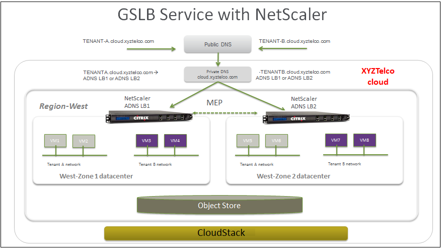
Tenant-A wishes to leverage the GSLB service provided by the xyztelco cloud. Tenant-A configures a GSLB rule to load balance traffic across virtual server 1 at Zone-1 and virtual server 2 at Zone-2. The domain name is provided as A.xyztelco.com. CloudStack orchestrates setting up GSLB virtual server 1 on the GSLB service provider at Zone-1. CloudStack binds virtual server 1 of Zone-1 and virtual server 2 of Zone-2 to GLSB virtual server 1. GSLB virtual server 1 is configured to start monitoring the health of virtual server 1 and 2 in Zone-1. CloudStack will also orchestrate setting up GSLB virtual server 2 on GSLB service provider at Zone-2. CloudStack will bind virtual server 1 of Zone-1 and virtual server 2 of Zone-2 to GLSB virtual server 2. GSLB virtual server 2 is configured to start monitoring the health of virtual server 1 and 2. CloudStack will bind the domain A.xyztelco.com to both the GSLB virtual server 1 and 2. At this point, Tenant-A service will be globally reachable at A.xyztelco.com. The private DNS server for the domain xyztelcom.com is configured by the admin out-of-band to resolve the domain A.xyztelco.com to the GSLB providers at both the zones, which are configured as ADNS for the domain A.xyztelco.com. A client when sends a DNS request to resolve A.xyztelcom.com, will eventually get DNS delegation to the address of GSLB providers at zone 1 and 2. A client DNS request will be received by the GSLB provider. The GSLB provider, depending on the domain for which it needs to resolve, will pick up the GSLB virtual server associated with the domain. Depending on the health of the virtual servers being load balanced, DNS request for the domain will be resolved to the public IP associated with the selected virtual server.
Configuring GSLB
To configure a GSLB deployment, you must first configure a standard load balancing setup for each zone. This enables you to balance load across the different servers in each zone in the region. Then on the NetScaler side, configure both NetScaler appliances that you plan to add to each zone as authoritative DNS (ADNS) servers. Next, create a GSLB site for each zone, configure GSLB virtual servers for each site, create GLSB services, and bind the GSLB services to the GSLB virtual servers. Finally, bind the domain to the GSLB virtual servers. The GSLB configurations on the two appliances at the two different zones are identical, although each sites load-balancing configuration is specific to that site.
Perform the following as a cloud administrator. As per the example given above, the administrator of xyztelco is the one who sets up GSLB:
In the cloud.dns.name global parameter, specify the DNS name of your tenant’s cloud that make use of the GSLB service.
On the NetScaler side, configure GSLB as given in Configuring Global Server Load Balancing (GSLB):
Configuring a standard load balancing setup.
Configure Authoritative DNS, as explained in Configuring an Authoritative DNS Service.
Configure a GSLB site with site name formed from the domain name details.
Configure a GSLB site with the site name formed from the domain name.
As per the example given above, the site names are A.xyztelco.com and B.xyztelco.com.
For more information, see Configuring a Basic GSLB Site.
Configurer un serveur virtuel GSLB
For more information, see Configuring a GSLB Virtual Server.
Configure a GSLB service for each virtual server.
For more information, see Configuring a GSLB Service.
Bind the GSLB services to the GSLB virtual server.
For more information, see Binding GSLB Services to a GSLB Virtual Server.
Bind domain name to GSLB virtual server. Domain name is obtained from the domain details.
For more information, see Binding a Domain to a GSLB Virtual Server.
In each zone that are participating in GSLB, add GSLB-enabled NetScaler device.
For more information, see Enabling GSLB in NetScaler.
As a domain administrator/ user perform the following:
Add a GSLB rule on both the sites.
Voir “Adding a GSLB Rule”.
Assign load balancer rules.
Prérequis et lignes directrives
The GSLB functionality is supported both Basic and Advanced zones.
GSLB is added as a new network service.
GSLB service provider can be added to a physical network in a zone.
The admin is allowed to enable or disable GSLB functionality at region level.
The admin is allowed to configure a zone as GSLB capable or enabled.
A zone shall be considered as GSLB capable only if a GSLB service provider is provisioned in the zone.
When users have VMs deployed in multiple availability zones which are GSLB enabled, they can use the GSLB functionality to load balance traffic across the VMs in multiple zones.
The users can use GSLB to load balance across the VMs across zones in a region only if the admin has enabled GSLB in that region.
The users can load balance traffic across the availability zones in the same region or different regions.
The admin can configure DNS name for the entire cloud.
The users can specify an unique name across the cloud for a globally load balanced service. The provided name is used as the domain name under the DNS name associated with the cloud.
The user-provided name along with the admin-provided DNS name is used to produce a globally resolvable FQDN for the globally load balanced service of the user. For example, if the admin has configured xyztelco.com as the DNS name for the cloud, and user specifies ‘foo’ for the GSLB virtual service, then the FQDN name of the GSLB virtual service is foo.xyztelco.com.
While setting up GSLB, users can select a load balancing method, such as round robin, for using across the zones that are part of GSLB.
The user shall be able to set weight to zone-level virtual server. Weight shall be considered by the load balancing method for distributing the traffic.
The GSLB functionality shall support session persistence, where series of client requests for particular domain name is sent to a virtual server on the same zone.
Statistics is collected from each GSLB virtual server.
Enabling GSLB in NetScaler
In each zone, add GSLB-enabled NetScaler device for load balancing.
Log in as administrator to the CloudStack UI.
Dans la barre de navigation de gauche, cliquer sur Infrastructure.
Dans Zones, cliquez sur Voir plus.
Choisir la zone avec laquelle vous voulez travailler.
Click the Physical Network tab, then click the name of the physical network.
In the Network Service Providers node of the diagram, click Configure.
You might have to scroll down to see this.
Citrix NetScaler.
Click Add NetScaler device and provide the following:
Pour les NetScaler :
- IP Address: The IP address of the SDX.
- Username/Password: The authentication credentials to access the device. CloudStack uses these credentials to access the device.
- Type: The type of device that is being added. It could be F5 Big Ip Load Balancer, NetScaler VPX, NetScaler MPX, or NetScaler SDX. For a comparison of the NetScaler types, see the CloudStack Administration Guide.
- Public interface: Interface of device that is configured to be part of the public network.
- Private interface: Interface of device that is configured to be part of the private network.
- GSLB service: Select this option.
- GSLB service Public IP: The public IP address of the NAT translator for a GSLB service that is on a private network.
- GSLB service Private IP: The private IP of the GSLB service.
- Number of Retries. Number of times to attempt a command on the device before considering the operation failed. Default is 2.
- Capacity: The number of networks the device can handle.
- Dedicated: When marked as dedicated, this device will be dedicated to a single account. When Dedicated is checked, the value in the Capacity field has no significance implicitly, its value is 1.
Cliquez sur OK.
Adding a GSLB Rule
Log in to the CloudStack UI as a domain administrator or user.
In the left navigation pane, click Region.
Select the region for which you want to create a GSLB rule.
In the Details tab, click View GSLB.
Cliquer sur Ajouter un GSLB.
The Add GSLB page is displayed as follows:
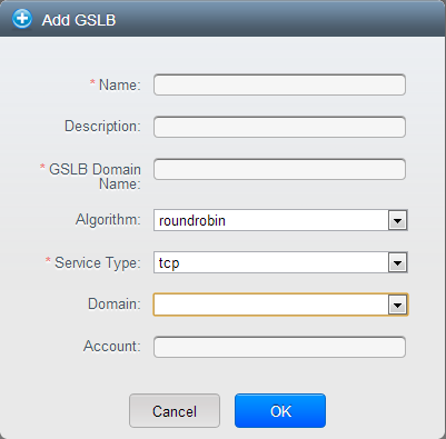
Spécifier les informations suivantes :
- Name: Name for the GSLB rule.
- Description: (Optional) A short description of the GSLB rule that can be displayed to users.
- GSLB Domain Name: A preferred domain name for the service.
- Algorithm: (Optional) The algorithm to use to load balance the traffic across the zones. The options are Round Robin, Least Connection, and Proximity.
- Service Type: The transport protocol to use for GSLB. The options are TCP and UDP.
- Domain: (Optional) The domain for which you want to create the GSLB rule.
- Account: (Optional) The account on which you want to apply the GSLB rule.
Cliquer OK pour confirmer.
Assigning Load Balancing Rules to GSLB
- Log in to the CloudStack UI as a domain administrator or user.
- In the left navigation pane, click Region.
- Select the region for which you want to create a GSLB rule.
- In the Details tab, click View GSLB.
- Select the desired GSLB.
- Click view assigned load balancing.
- Click assign more load balancing.
- Select the load balancing rule you have created for the zone.
Cliquer OK pour confirmer.
Limitations connues
Currently, CloudStack does not support orchestration of services across the zones. The notion of services and service providers in region are to be introduced.
Plages IP invités
Les plages d’IP pour le trafic réseau invité est configuré par compte par l’utilisateur. Cela permet aux utilisateurs de configurer leur réseau de façon qui va activer le lien VPN entre son réseau invité et ses clients.
Sur des réseaux partagés dans une zone Basique et dans les réseaux Avancés avec Groupes de Sécurité, vous aurez la souplesse d’ajouter de nombreuses plages d’adresses IP invité depuis différents sous-réseaux. Vous pouvez ajouter ou supprimer une plage IP à la fois. Pour plus d’informations, voir “A propos des plages IP multiples”.
Acquérir une nouvelle adresse IP
Se connecter à l’interface de CloudStack comme administrateur ou utilisateur final.
Dans la navigation à gauche, choisissez Réseau.
Cliquez sur le nom du réseau avec lequel vous souhaitez travailler.
Cliquez sur Voir les adresses IP.
Cliquer sur Acquérir une nouvelle IP.
La fenêtre Acquérir une nouvelle IP est affichée.
Spécifier si vous voulez une IP transverse à la zone ou non.
Si vous voulez une IP portable, cliquez sur Oui dans la boîte de dialogue de confirmation. Si vous voulez une IP public normale, cliquez sur Non.
Pour plus d’information sur l’IP Portable, voir “IPs Portables”.
Après quelques instants, la nouvelle adresse IP devrait apparaître avec l’état Allouée. Vous pouvez utiliser l’adresse IP dans la redirection de port ou les règles de NATage statiques.
Libérer une adresse IP
Lorsque la dernière règle pour une adresse IP est supprimée, vous pouvez libérer cette adresse IP. L’adresse IP appartient toujours au VPC ; toutefois elle peut être à nouveau reprise pour n’importe quel réseau invité.
Se connecter à l’interface de CloudStack comme administrateur ou utilisateur final.
Dans la navigation à gauche, choisissez Réseau.
Cliquez sur le nom du réseau avec lequel vous souhaitez travailler.
Cliquez sur Voir les adresses IP.
Cliquer sur l’adresse IP que vous voulez libérer.
Cliquer sur le bouton Libérer.

Static NAT
Une règle de NAT statique associe une adresse IP publique à l’adresse IP privée d’une VM afin de permettre le trafic Internet vers la machine virtuelle. L’adresse IP publique reste toujours la même, raison pour laquelle cette solution est appelée static NAT. Cette section explique comment activer ou désactiver le static NAT pour une adresse IP particulière.
Activer ou désactiver un NAT Statique
Si les règles de redirection de port sont déjà mise en oeuvre pour une adresse IP, vous ne pouvez pas activer le static NAT pour cette IP.
Si une VM invitée fait partie de plus d’un réseau, les règles de static NAT ne fonctionneront uniquement si elle sont définies sur le réseau par défaut.
Se connecter à l’interface de CloudStack comme administrateur ou utilisateur final.
Dans la navigation à gauche, choisissez Réseau.
Cliquez sur le nom du réseau avec lequel vous souhaitez travailler.
Cliquez sur Voir les adresses IP.
Cliquer sur l’adresse IP avec laquelle vous voulez travailler.
Cliquer sur le bouton Static NAT
 .
.Le bouton bascule entre Activer et Désactiver, selon que le static NAT est actuellement activé pour l’adresse IP.
Si vous activez le static NAT, une boite de dialogue apparaît dans laquelle vous pouvez choisir la VM cible et cliquer sur Appliquer.
Redirection IP et pare-feu
By default, all incoming traffic to the public IP address is rejected. All outgoing traffic from the guests is also blocked by default.
To allow outgoing traffic, follow the procedure in Egress Firewall Rules in an Advanced Zone.
To allow incoming traffic, users may set up firewall rules and/or port forwarding rules. For example, you can use a firewall rule to open a range of ports on the public IP address, such as 33 through 44. Then use port forwarding rules to direct traffic from individual ports within that range to specific ports on user VMs. For example, one port forwarding rule could route incoming traffic on the public IP’s port 33 to port 100 on one user VM’s private IP.
Règles du pare-feu
By default, all incoming traffic to the public IP address is rejected by the firewall. To allow external traffic, you can open firewall ports by specifying firewall rules. You can optionally specify one or more CIDRs to filter the source IPs. This is useful when you want to allow only incoming requests from certain IP addresses.
You cannot use firewall rules to open ports for an elastic IP address. When elastic IP is used, outside access is instead controlled through the use of security groups. See “Adding a Security Group”.
In an advanced zone, you can also create egress firewall rules by using the virtual router. For more information, see “Egress Firewall Rules in an Advanced Zone”.
Firewall rules can be created using the Firewall tab in the Management Server UI. This tab is not displayed by default when CloudStack is installed. To display the Firewall tab, the CloudStack administrator must set the global configuration parameter firewall.rule.ui.enabled to “true.”
Pour créer une règle de pare-feu :
Se connecter à l’interface de CloudStack comme administrateur ou utilisateur final.
Dans la navigation à gauche, choisissez Réseau.
Cliquez sur le nom du réseau avec lequel vous souhaitez travailler.
Cliquez sur Voir les adresses IP.
Cliquer sur l’adresse IP avec laquelle vous voulez travailler.
- Click the Configuration tab and fill in the following values.
- Source CIDR: (Optional) To accept only traffic from IP addresses within a particular address block, enter a CIDR or a comma-separated list of CIDRs. Example: 192.168.0.0/22. Leave empty to allow all CIDRs.
- Protocol: The communication protocol in use on the opened port(s).
- Start Port and End Port: The port(s) you want to open on the firewall. If you are opening a single port, use the same number in both fields
- ICMP Type and ICMP Code: Used only if Protocol is set to ICMP. Provide the type and code required by the ICMP protocol to fill out the ICMP header. Refer to ICMP documentation for more details if you are not sure what to enter
Cliquer sur Ajouter.
Egress Firewall Rules in an Advanced Zone
The egress traffic originates from a private network to a public network, such as the Internet. By default, the egress traffic is blocked in default network offerings, so no outgoing traffic is allowed from a guest network to the Internet. However, you can control the egress traffic in an Advanced zone by creating egress firewall rules. When an egress firewall rule is applied, the traffic specific to the rule is allowed and the remaining traffic is blocked. When all the firewall rules are removed the default policy, Block, is applied.
Prérequis et lignes directrives
Consider the following scenarios to apply egress firewall rules:
- Egress firewall rules are supported on Juniper SRX and virtual router.
- The egress firewall rules are not supported on shared networks.
- Allow the egress traffic from specified source CIDR. The Source CIDR is part of guest network CIDR.
- Allow the egress traffic with protocol TCP,UDP,ICMP, or ALL.
- Allow the egress traffic with protocol and destination port range. The port range is specified for TCP, UDP or for ICMP type and code.
- The default policy is Allow for the new network offerings, whereas on upgrade existing network offerings with firewall service providers will have the default egress policy Deny.
Configuring an Egress Firewall Rule
Se connecter à l’interface de CloudStack comme administrateur ou utilisateur final.
Dans la navigation à gauche, choisissez Réseau.
In Select view, choose Guest networks, then click the Guest network you want.
To add an egress rule, click the Egress rules tab and fill out the following fields to specify what type of traffic is allowed to be sent out of VM instances in this guest network:
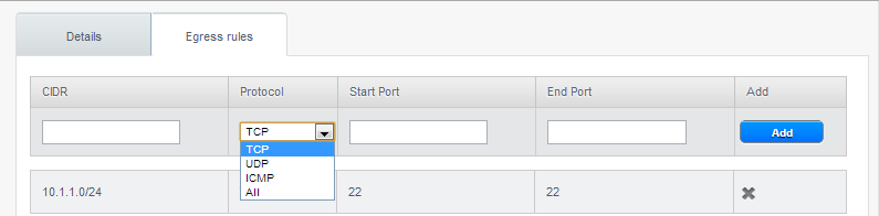
- CIDR: (Add by CIDR only) To send traffic only to the IP addresses within a particular address block, enter a CIDR or a comma-separated list of CIDRs. The CIDR is the base IP address of the destination. For example, 192.168.0.0/22. To allow all CIDRs, set to 0.0.0.0/0.
- Protocol: The networking protocol that VMs uses to send outgoing traffic. The TCP and UDP protocols are typically used for data exchange and end-user communications. The ICMP protocol is typically used to send error messages or network monitoring data.
- Start Port, End Port: (TCP, UDP only) A range of listening ports that are the destination for the outgoing traffic. If you are opening a single port, use the same number in both fields.
- ICMP Type, ICMP Code: (ICMP only) The type of message and error code that are sent.
Cliquer sur Ajouter.
Configurer la Stratégie par défaut Egress
The default egress policy for Isolated guest network is configured by using Network offering. Use the create network offering option to determine whether the default policy should be block or allow all the traffic to the public network from a guest network. Use this network offering to create the network. If no policy is specified, by default all the traffic is allowed from the guest network that you create by using this network offering.
Vous avez 2 options : Autoriser et Refuser.
Autoriser
If you select Allow for a network offering, by default egress traffic is allowed. However, when an egress rule is configured for a guest network, rules are applied to block the specified traffic and rest are allowed. If no egress rules are configured for the network, egress traffic is accepted.
Refuser
If you select Deny for a network offering, by default egress traffic for the guest network is blocked. However, when an egress rules is configured for a guest network, rules are applied to allow the specified traffic. While implementing a guest network, CloudStack adds the firewall egress rule specific to the default egress policy for the guest network.
This feature is supported only on virtual router and Juniper SRX.
Create a network offering with your desirable default egress policy:
Se connecter avec les droits d’administrateur à l’interface CloudStack.
Dans la barre de navigation de gauche, cliquer sur Offres de Service.
Dans Sélectionner une offre, choisir une offre réseau.
Cliquer sur Ajouter une offre de réseau.
- In the dialog, make necessary choices, including firewall provider.
- In the Default egress policy field, specify the behaviour.
Cliquez sur OK.
Create an isolated network by using this network offering.
Based on your selection, the network will have the egress public traffic blocked or allowed.
Redirection de port
A port forward service is a set of port forwarding rules that define a policy. A port forward service is then applied to one or more guest VMs. The guest VM then has its inbound network access managed according to the policy defined by the port forwarding service. You can optionally specify one or more CIDRs to filter the source IPs. This is useful when you want to allow only incoming requests from certain IP addresses to be forwarded.
A guest VM can be in any number of port forward services. Port forward services can be defined but have no members. If a guest VM is part of more than one network, port forwarding rules will function only if they are defined on the default network
You cannot use port forwarding to open ports for an elastic IP address. When elastic IP is used, outside access is instead controlled through the use of security groups. See Security Groups.
Pour configurer la redirection de port :
Se connecter à l’interface de CloudStack comme administrateur ou utilisateur final.
- If you have not already done so, add a public IP address range to a zone in CloudStack. See Adding a Zone and Pod in the Installation Guide.
- Add one or more VM instances to CloudStack.
Dans la barre de navigation de gauche, cliquer sur Réseau.
- Click the name of the guest network where the VMs are running.
- Choose an existing IP address or acquire a new IP address. See “Acquiring a New IP Address”. Click the name of the IP address in the list.
Cliquer sur l’onglet Configuration.
- In the Port Forwarding node of the diagram, click View All.
Remplissez les champs suivants:
- Public Port: The port to which public traffic will be addressed on the IP address you acquired in the previous step.
- Private Port: The port on which the instance is listening for forwarded public traffic.
- Protocol: The communication protocol in use between the two ports
Cliquer sur Ajouter.
Répartition de charge IP
L’utilisateur peut choisir d’associer la même IP publique pour plusieurs invités. CloudStack implémente un répartiteur de charge de niveau TCP avec les règles suivantes.
- Round-robin
La plus petite connexion
IP source
C’est similaire à la redirection de port mais la destination peut être plusieurs adresses IP.
DNS et DHCP
Le routeur virtuel fourni les services DNS et DHCP aux invités. Il relaie les requêtes DNS aux serveurs DNS configurés dans la Zone disponible.
Accès distant VPN
CloudStack account owners can create virtual private networks (VPN) to access their virtual machines. If the guest network is instantiated from a network offering that offers the Remote Access VPN service, the virtual router (based on the System VM) is used to provide the service. CloudStack provides a L2TP-over-IPsec-based remote access VPN service to guest virtual networks. Since each network gets its own virtual router, VPNs are not shared across the networks. VPN clients native to Windows, Mac OS X and iOS can be used to connect to the guest networks. The account owner can create and manage users for their VPN. CloudStack does not use its account database for this purpose but uses a separate table. The VPN user database is shared across all the VPNs created by the account owner. All VPN users get access to all VPNs created by the account owner.
Note
Make sure that not all traffic goes through the VPN. That is, the route installed by the VPN should be only for the guest network and not for all traffic.
- Road Warrior / Remote Access. Users want to be able to connect securely from a home or office to a private network in the cloud. Typically, the IP address of the connecting client is dynamic and cannot be preconfigured on the VPN server.
- Site to Site. In this scenario, two private subnets are connected over the public Internet with a secure VPN tunnel. The cloud user’s subnet (for example, an office network) is connected through a gateway to the network in the cloud. The address of the user’s gateway must be preconfigured on the VPN server in the cloud. Note that although L2TP-over-IPsec can be used to set up Site-to-Site VPNs, this is not the primary intent of this feature. For more information, see “Setting Up a Site-to-Site VPN Connection”.
Configuring Remote Access VPN
To set up VPN for the cloud:
Se connecter à l’interface de CloudStack comme administrateur ou utilisateur final.
- In the left navigation, click Global Settings.
- Set the following global configuration parameters.
- remote.access.vpn.client.ip.range - The range of IP addresses to be allocated to remote access VPN clients. The first IP in the range is used by the VPN server.
- remote.access.vpn.psk.length - Length of the IPSec key.
- remote.access.vpn.user.limit - Maximum number of VPN users per account.
To enable VPN for a particular network:
Log in as a user or administrator to the CloudStack UI.
In the left navigation, click Network.
Click the name of the network you want to work with.
Cliquez sur Voir les adresses IP.
Click one of the displayed IP address names.
Click the Enable VPN button.

The IPsec key is displayed in a popup window.
Configuring Remote Access VPN in VPC
On enabling Remote Access VPN on a VPC, any VPN client present outside the VPC can access VMs present in the VPC by using the Remote VPN connection. The VPN client can be present anywhere except inside the VPC on which the user enabled the Remote Access VPN service.
To enable VPN for a VPC:
Log in as a user or administrator to the CloudStack UI.
In the left navigation, click Network.
Dans la vue de Sélection, choisissez VPC.
All the VPCs that you have created for the account is listed in the page.
Click the Configure button of the VPC.
For each tier, the following options are displayed:
- Internal LB
- Public LB IP
- Static NAT
Machines Virtuelles
- CIDR
The following router information is displayed:
Passerelles privées
Adresses IP publiques
- Site-to-Site VPNs
Listes d’ACL réseau
In the Router node, select Public IP Addresses.
The IP Addresses page is displayed.
Click Source NAT IP address.
Click the Enable VPN button.
Click OK to confirm. The IPsec key is displayed in a pop-up window.
Now, you need to add the VPN users.
- Click the Source NAT IP.
- Select the VPN tab.
- Add the username and the corresponding password of the user you wanted to add.
Cliquer sur Ajouter.
- Repeat the same steps to add the VPN users.
Setting Up a Site-to-Site VPN Connection
A Site-to-Site VPN connection helps you establish a secure connection from an enterprise datacenter to the cloud infrastructure. This allows users to access the guest VMs by establishing a VPN connection to the virtual router of the account from a device in the datacenter of the enterprise. You can also establish a secure connection between two VPC setups or high availability zones in your environment. Having this facility eliminates the need to establish VPN connections to individual VMs.
The difference from Remote VPN is that Site-to-site VPNs connects entire networks to each other, for example, connecting a branch office network to a company headquarters network. In a site-to-site VPN, hosts do not have VPN client software; they send and receive normal TCP/IP traffic through a VPN gateway.
The supported endpoints on the remote datacenters are:
- Cisco ISR with IOS 12.4 or later
- Juniper J-Series routers with JunOS 9.5 or later
- CloudStack virtual routers
Note
In addition to the specific Cisco and Juniper devices listed above, the expectation is that any Cisco or Juniper device running on the supported operating systems are able to establish VPN connections.
To set up a Site-to-Site VPN connection, perform the following:
Create a Virtual Private Cloud (VPC).
Create a VPN Customer Gateway.
Create a VPN gateway for the VPC that you created.
Create VPN connection from the VPC VPN gateway to the customer VPN gateway.
Creating and Updating a VPN Customer Gateway
Note
A VPN customer gateway can be connected to only one VPN gateway at a time.
To add a VPN Customer Gateway:
Se connecter à l’interface de CloudStack comme administrateur ou utilisateur final.
Dans la navigation à gauche, choisissez Réseau.
In the Select view, select VPN Customer Gateway.
Click Add VPN Customer Gateway.
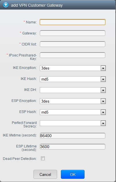
Fournir l’information suivante :
Name: A unique name for the VPN customer gateway you create.
Gateway: The IP address for the remote gateway.
CIDR list: The guest CIDR list of the remote subnets. Enter a CIDR or a comma-separated list of CIDRs. Ensure that a guest CIDR list is not overlapped with the VPC’s CIDR, or another guest CIDR. The CIDR must be RFC1918-compliant.
IPsec Preshared Key: Preshared keying is a method where the endpoints of the VPN share a secret key. This key value is used to authenticate the customer gateway and the VPC VPN gateway to each other. The sequence cannot contain a newline or double-quote.
Note
The IKE peers (VPN end points) authenticate each other by computing and sending a keyed hash of data that includes the Preshared key. If the receiving peer is able to create the same hash independently by using its Preshared key, it knows that both peers must share the same secret, thus authenticating the customer gateway.
IKE Encryption: The Internet Key Exchange (IKE) policy for phase-1. The supported encryption algorithms are AES128, AES192, AES256, and 3DES. Authentication is accomplished through the Preshared Keys.
Note
The phase-1 is the first phase in the IKE process. In this initial negotiation phase, the two VPN endpoints agree on the methods to be used to provide security for the underlying IP traffic. The phase-1 authenticates the two VPN gateways to each other, by confirming that the remote gateway has a matching Preshared Key.
IKE Hash: The IKE hash for phase-1. The supported hash algorithms are SHA1 and MD5.
IKE DH: A public-key cryptography protocol which allows two parties to establish a shared secret over an insecure communications channel. The 1536-bit Diffie-Hellman group is used within IKE to establish session keys. The supported options are None, Group-5 (1536-bit) and Group-2 (1024-bit).
ESP Encryption: Encapsulating Security Payload (ESP) algorithm within phase-2. The supported encryption algorithms are AES128, AES192, AES256, and 3DES.
Note
The phase-2 is the second phase in the IKE process. The purpose of IKE phase-2 is to negotiate IPSec security associations (SA) to set up the IPSec tunnel. In phase-2, new keying material is extracted from the Diffie-Hellman key exchange in phase-1, to provide session keys to use in protecting the VPN data flow.
ESP Hash: Encapsulating Security Payload (ESP) hash for phase-2. Supported hash algorithms are SHA1 and MD5.
Perfect Forward Secrecy: Perfect Forward Secrecy (or PFS) is the property that ensures that a session key derived from a set of long-term public and private keys will not be compromised. This property enforces a new Diffie-Hellman key exchange. It provides the keying material that has greater key material life and thereby greater resistance to cryptographic attacks. The available options are None, Group-5 (1536-bit) and Group-2 (1024-bit). The security of the key exchanges increase as the DH groups grow larger, as does the time of the exchanges.
Note
When PFS is turned on, for every negotiation of a new phase-2 SA the two gateways must generate a new set of phase-1 keys. This adds an extra layer of protection that PFS adds, which ensures if the phase-2 SA’s have expired, the keys used for new phase-2 SA’s have not been generated from the current phase-1 keying material.
IKE Lifetime (seconds): The phase-1 lifetime of the security association in seconds. Default is 86400 seconds (1 day). Whenever the time expires, a new phase-1 exchange is performed.
ESP Lifetime (seconds): The phase-2 lifetime of the security association in seconds. Default is 3600 seconds (1 hour). Whenever the value is exceeded, a re-key is initiated to provide a new IPsec encryption and authentication session keys.
Dead Peer Detection: A method to detect an unavailable Internet Key Exchange (IKE) peer. Select this option if you want the virtual router to query the liveliness of its IKE peer at regular intervals. It’s recommended to have the same configuration of DPD on both side of VPN connection.
Cliquez sur OK.
Updating and Removing a VPN Customer Gateway
You can update a customer gateway either with no VPN connection, or related VPN connection is in error state.
Se connecter à l’interface de CloudStack comme administrateur ou utilisateur final.
Dans la navigation à gauche, choisissez Réseau.
- In the Select view, select VPN Customer Gateway.
- Select the VPN customer gateway you want to work with.
- To modify the required parameters, click the Edit VPN Customer
Gateway button
- To remove the VPN customer gateway, click the Delete VPN Customer
Gateway button

Cliquez sur OK.
Creating a VPN gateway for the VPC
Se connecter à l’interface de CloudStack comme administrateur ou utilisateur final.
Dans la navigation à gauche, choisissez Réseau.
Dans la vue de Sélection, choisissez VPC.
All the VPCs that you have created for the account is listed in the page.
Click the Configure button of the VPC to which you want to deploy the VMs.
The VPC page is displayed where all the tiers you created are listed in a diagram.
For each tier, the following options are displayed:
- Internal LB
- Public LB IP
- Static NAT
Machines Virtuelles
- CIDR
The following router information is displayed:
Passerelles privées
Adresses IP publiques
- Site-to-Site VPNs
Listes d’ACL réseau
Select Site-to-Site VPN.
If you are creating the VPN gateway for the first time, selecting Site-to-Site VPN prompts you to create a VPN gateway.
In the confirmation dialog, click Yes to confirm.
Within a few moments, the VPN gateway is created. You will be prompted to view the details of the VPN gateway you have created. Click Yes to confirm.
The following details are displayed in the VPN Gateway page:
Adresse IP
Compte
Domaine
Creating a VPN Connection
Note
CloudStack supports creating up to 8 VPN connections.
Se connecter à l’interface de CloudStack comme administrateur ou utilisateur final.
Dans la navigation à gauche, choisissez Réseau.
Dans la vue de Sélection, choisissez VPC.
All the VPCs that you create for the account are listed in the page.
Click the Configure button of the VPC to which you want to deploy the VMs.
The VPC page is displayed where all the tiers you created are listed in a diagram.
Cliquer sur l’icône Paramètres.
For each tier, the following options are displayed:
- Internal LB
- Public LB IP
- Static NAT
Machines Virtuelles
- CIDR
The following router information is displayed:
Passerelles privées
Adresses IP publiques
- Site-to-Site VPNs
Listes d’ACL réseau
Select Site-to-Site VPN.
The Site-to-Site VPN page is displayed.
From the Select View drop-down, ensure that VPN Connection is selected.
Click Create VPN Connection.
The Create VPN Connection dialog is displayed:
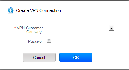
Select the desired customer gateway.
Select Passive if you want to establish a connection between two VPC virtual routers.
If you want to establish a connection between two VPC virtual routers, select Passive only on one of the VPC virtual routers, which waits for the other VPC virtual router to initiate the connection. Do not select Passive on the VPC virtual router that initiates the connection.
Cliquer OK pour confirmer.
Within a few moments, the VPN Connection is displayed.
The following information on the VPN connection is displayed:
Adresse IP
Passerelle
Etat
- IPSec Preshared Key
- IKE Policy
- ESP Policy
Site-to-Site VPN Connection Between VPC Networks
CloudStack provides you with the ability to establish a site-to-site VPN connection between CloudStack virtual routers. To achieve that, add a passive mode Site-to-Site VPN. With this functionality, users can deploy applications in multiple Availability Zones or VPCs, which can communicate with each other by using a secure Site-to-Site VPN Tunnel.
This feature is supported on all the hypervisors.
Create two VPCs. For example, VPC A and VPC B.
For more information, see “Configurer un Cloud Privé Virtuel”.
Create VPN gateways on both the VPCs you created.
For more information, see “Creating a VPN gateway for the VPC”.
Create VPN customer gateway for both the VPCs.
For more information, see “Creating and Updating a VPN Customer Gateway”.
Enable a VPN connection on VPC A in passive mode.
For more information, see “Creating a VPN Connection”.
Ensure that the customer gateway is pointed to VPC B. The VPN connection is shown in the Disconnected state.
Enable a VPN connection on VPC B.
Ensure that the customer gateway is pointed to VPC A. Because virtual router of VPC A, in this case, is in passive mode and is waiting for the virtual router of VPC B to initiate the connection, VPC B virtual router should not be in passive mode.
The VPN connection is shown in the Disconnected state.
Creating VPN connection on both the VPCs initiates a VPN connection. Wait for few seconds. The default is 30 seconds for both the VPN connections to show the Connected state.
Restarting and Removing a VPN Connection
Se connecter à l’interface de CloudStack comme administrateur ou utilisateur final.
Dans la navigation à gauche, choisissez Réseau.
Dans la vue de Sélection, choisissez VPC.
All the VPCs that you have created for the account is listed in the page.
Click the Configure button of the VPC to which you want to deploy the VMs.
The VPC page is displayed where all the tiers you created are listed in a diagram.
Cliquer sur l’icône Paramètres.
For each tier, the following options are displayed:
- Internal LB
- Public LB IP
- Static NAT
Machines Virtuelles
- CIDR
The following router information is displayed:
Passerelles privées
Adresses IP publiques
- Site-to-Site VPNs
Listes d’ACL réseau
Select Site-to-Site VPN.
The Site-to-Site VPN page is displayed.
From the Select View drop-down, ensure that VPN Connection is selected.
All the VPN connections you created are displayed.
Select the VPN connection you want to work with.
The Details tab is displayed.
To remove a VPN connection, click the Delete VPN connection button

To restart a VPN connection, click the Reset VPN connection button present in the Details tab.

A propos du routage Inter-VLAN (Applications NTiers)
Le routage Inter-VLAN (Applications nTiers) est la capacité de router le réseau entre les VLANs. Cette fonctionnalité vous permet de bâtir des Clouds Privés Virtuels (VPC), un segment isolé de votre cloud, qui peut contenir des applications multi-tier. Ces tiers sont déployés sur des différents VLANs qui peuvent communiquer avec les uns les autres. Vous provisionnez les VLANs aux tiers que vous créez, et les VMs peuvent être déployées sur différents tiers. Les VLANs sont connectés à un routeur virtuel, ce qui facilite la communication entre les VMs. En effet, vous pouvez segmenter les VMs au moyen de VLANs en différents réseaux qui peuvent accueillir des applications multi-tier, comme le Web, l’Application ou la base de données. Une telle segmentation au moyen de VLANs sépare les VMs de l’application logiquement pour plus de sécurité et pour des domaines de broadcasts réduit, alors qu’elles restent connectées physiquement au même périphérique.
Cette fonctionnalité est supportée sur les hyperviseurs XenServer, KVM et VMware.
Les avantages majeurs sont :
L’administrateur peut déployer un ensemble de VLAN et permettre aux utilisateurs de déployer des VM sur ces VLAN. Un VLAN invité est alloué aléatoirement à un compte à partir d’un ensemble prédéfini de VLAN invités. Toutes les machines virtuelles d’un segment spécifique d’un compte résident sur le VLAN invité réservé à ce compte.
Note
Un VLAN alloué pour un compte ne peut pas être partagé entre plusieurs comptes.
L’administrateur peut autoriser les utilisateurs à créer leur propre VPC et déployer l’application. Dans ce scénario, les VM qui appartiennent au compte sont déployées sur les VLAN alloués à ce compte.
A la fois les administrateurs et les utilisateurs peuvent créer plusieurs VPC. L’interface NIC du réseau invité est connectée au routeur virtuel du VPC lorsque la première VM est déployée dans un segment.
L’administrateur peut créer les passerelles suivantes pour envoyer ou recevoir le trafic depuis les VM :
Passerelle VPN : Pour plus d’informations, consultez “Créer une passerelle VPN pour le VPC” <#creating-a-vpn-gateway-for-the-vpc>`_.
Passerelle publique : La passerelle publique pour le VPC est ajoutée au routeur virtuel lorsque le routeur virtuel est créé pour le VPC. La passerelle publique n’est pas exposée aux utilisateurs finaux. Vous n’êtes pas autorisés à la lister, ni autorisé à créer des routes statiques.
Passerelle privée : Pour plus d’informations consultez “Ajouter une passerelle privée à un VPC”.
Les administrateurs et les utilisateurs peuvent créer diverses combinaisons possibles de destinations-passerelles. Cependant, une seule passerelle de chaque type peut être utilisée dans un déploiement.
Par exemple :
VLAN et Passerelle publique : Par exemple, une application est déployée dans le cloud, et les VM des serveurs d’applications Web communiquent avec Internet.
VLAN, passerelle VPN et passerelle publique : Par exemple, une application est déployée dans le cloud ; les VM des serveurs d’applications Web communiquent avec Internet ; et les VM de base de données communiquent avec les dispositifs en local.
L’administrateur peut définir la liste de contrôle d’accès réseau (ACL) sur le routeur virtuel pour filtrer le trafic entre les VLAN ou entre Internet et un VLAN. Vous pouvez définir des ACL en fonction du CIDR, de la plage de ports, du protocole, du code de type (si le protocole ICMP est sélectionné) et du type Ingress / Egress.
La figure suivante montre les scénarios possibles d’une configuration Inter-VLAN :
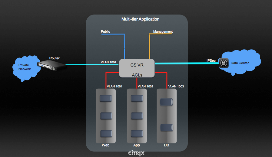
Pour configurer un déploiement multi-tiers Inter-VLAN, voir “Configurer un Cloud Privé Virtuel”.
Configurer un Cloud Privé Virtuel
A propos des Clouds Privés Virtuels
Un Cloud Privé Virtuel CloudStack est une partie privée, isolée de CloudStack. Un VPC peut avoir sa propre topologie de réseau virtuel qui ressemble à un réseau physique traditionnel. Vous pouvez lancer des VMs dans le réseau virtuel qui peuvent avoir des adresses privées dans l’intervalle de votre choix, par exemple : 10.10.10.0/16. Vous pouvez définir des parties de réseau dans l’étendue du réseau de votre VPC, permettant le regroupement des types d’instances similaires en fonction de leur intervalle d’adresse IP.
Par exemple, si un VPC dispose de la plage privée d’adresses IP 10.0.0.0/16, ses réseaux invités peuvent être dans les plages réseaux 10.0.1.0/24, 10.0.2.0/24, 10.0.3.0/24, etc.
Composants majeurs d’un VPC
Un VPC est constitué des composants réseaux suivants :
VPC: Un VPC agit comme un conteneur pour plusieurs réseaux isolés qui peuvent communiquer les uns les autres via son routeur virtuel.
Segments réseaux : chaque segment agit comme un réseau isolé avec ses propres VLANs et listes CIDR, dans lequel vous pouvez placer des groupes de ressources, comme des VM. Les segments sont segmentés par l’utilisation des VLANs. L’interface de chaque segment agit comme sa passerelle.
Routeur Virtuel : Un routeur virtuel est automatiquement créé et démarré lorsque vous créez un VPC. Le routeur virtuel connecte les segments et dirige le trafic entre la passerelle publique, les passerelles VPN et les instances NAT. Pour chaque segment, une interface et une IP correspondante existent dans le routeur virtuel. Le routeur virtuel fourni les services DNS et DHCP via ses IP.
Passerelle publique : Le trafic vers et provenant d’Internet est routé vers le VPC par la passerelle publique. Dans un VPC, la passerelle publique n’est pas exposée à l’utilisateur final ; en conséquence, les routes statiques ne sont pas supportées pour la passerelle publique.
Passerelle privée : tout le trafic provenant ou à destination d’un réseau privé est routé vers le VPC par la passerelle privée. Pour plus d’information, voir “Ajouter une passerelle privée à un VPC”.
Passerelle VPN : Le pendant VPC d’une connexion VPN.
Connexion VPN site-à-site : Une connexion VPN matérielle entre votre PVC et votre datacenter, votre réseau domestique ou autres installations. Pour plus d’information, voir “Setting Up a Site-to-Site VPN Connection”.
Passerelle client : le pendant client d’une connexion VPN. Pour plus d’informations, voir “Créer et mettre à jour une passerelle client”.
Instance NAT : Une instance qui fourni la translation de port pour que les instances puissent accéder à Internet via la passerelle publique. Pour plus d’informations, voir “Enabling or Disabling Static NAT on a VPC”.
ACL Réseau : Une ACL réseau est un groupe d’entrées d’ACL réseau. Les entrées d’ACL réseau ne sont rien d’autre qu’un nombre de règles qui sont évaluées dans l’ordre, en commençant par la règle avec le plus petit numéro. Ces règles déterminent si le trafic est autorisé en entrée ou en sortie de n’importe quel segment associé avec l’ACL réseau. Pour plus d’informations, voir “Configurer une liste de contrôle d’accès réseau”.
Architecture Réseau dans un VPC
Dans un VPC, les quatres options basiques d’architectures réseaux suivantes sont présentes :
VPC avec une passerelle publique seulement
VPC avec des passerelles publiques et privées
VPC avec des passerelles publiques et privées et un accès VPN site à site
VPC avec une passerelle privée seulement et un accès VPN site à site
Options de connectivité pour un VPC
Vous pouvez connecter votre VPC à :
à Internet en passant par la passerelle publique.
au centre de données de l’entreprise en utilisant une connexion VPN site à site en passant par la passerelle VPN.
A la fois à Internet et à votre centre de données interne en utilisant à la fois la passerelle publique et une passerelle VPN.
Considérations sur le réseau du VPC
Prendre en compte ce qui suit avant de créer un VPC :
Un VPC, par défaut, est créé dans l’état activé.
Un VPC peut être créé dans une zone avancée seulement, et ne peut pas appartenir à plus d’une zone à la fois.
Le nombre par défaut de VPC qu’un compte peut créer est de 20. Toutefois, vous pouvez le changer en utilisant le paramètre global max.accounts.vpcs, qui contrôle le nombre maximum de VPCs qu’un compte est autorisé à créer.
Le nombre par défaut de segment qu’un compte peut créer dans un VPC est de 3. Vous pouvez configurer ce nombre en utilisant le paramètre vpc.max.networks.
Chaque segment devrait avoir un CIDR unique dans le VPC. Assurez vous que le CIDR du segment est bien dans l’intervalle CIDR du VPC.
Un segment n’appartient qu’à un seul VPC.
Tout segment réseau à l’intérieur du VPC doit appartenir au même compte.
Lorsqu’un VPC est créé, par défaut, une IP Source NAT lui est allouée. L’adresse IP source NAT est libérée seulement lorsque le VPC est supprimé.
Une IP publique ne peut être utilisée que pour un seul besoin à la fois. Si l’IP est une IP source NAT, elle ne pourra pas être utilisée pour le NAT Statique ou la redirection de port.
Les instances peuvent seulement avoir une adresse IP privée que vous provisionnez. Pour communiquer avec Internet, activer le NAT pour une instance que vous lancez dans votre VPC.
Seulement les nouveaux réseaux peuvent être ajoutés à un VPC. Le nombre maximum de réseaux par VPC est limité par la valeur que vous spécifiez dans le paramètre vpc.max.networks. La valeur par défaut est trois.
La service de répartition de charge ne peut être supporté que par un seul segment à l’intérieur du VPC.
Si une adresse IP est attribuée à un segment :
Cette IP ne peut pas être utilisée par plus d’un segment à la fois dans le VPC. Par exemple, si vous avez les segments A et B et une IP1 publique, vous pouvez créer une règle de transmission de port en utilisant l’IP soit pour A ou B mais pas pour les deux.
Cette IP ne peut pas être utilisée pour du NAT Statique, pour la répartition de charge ou pour les règles de transmission de port pour un autre réseau invité au sein du VPC.
Les accès distants VPN ne sont pas supportés dans les réseaux du VPC.
Ajouter un Cloud Privé Virtuel
Lorsque vous créer le VPC, vous fournissez simplement la zone et un ensemble d’adresses IP pour l’espace d’adresse du réseau du VPC. Vous spécifiez cet ensemble d’adresses dans le format d’un bloc Classless Inter-Domain Routing (CIDR).
Se connecter à l’interface de CloudStack comme administrateur ou utilisateur final.
Dans la navigation à gauche, choisissez Réseau.
Dans la vue de Sélection, choisissez VPC.
Cliquer sur Ajouter VPC. La page Ajouter VPC est affichée comme suivant :
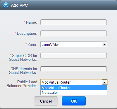
Fournir l’information suivante :
Nom : Un nom court pour le VPC que vous êtes en train de créer.
Description : Une description courte du VPC.
Zone : Choisir la zone dans laquelle vous voulez que le VPC soit disponible.
Super CIDR pour les réseaux invités : définir l’intervalle CIDR pour tous les segments (réseaux invités) au sein du VPC. Lorsque vous créez un segment, assurez vous que son CIDR soit compris dans la valeur du Super CIDR que vous avez entré. Le CIDR doit être conforme à la RFC1918.
Domaine DNS pour les réseaux invités : si vous voulez assigner un nom de domaine spécial, spécifier le suffixe DNS. Ce paramètre est appliqué à tous les segments au sein du VPC. Cela implique que tous les segments que vous créez dans le VPC appartiennent au même domaine DNS. Si le paramètre n’est pas spécifié, un nom de domaine DNS est généré automatiquement.
Fournisseur publique de répartition de charge : Vous avez deux options : Routeur Virtuel VPC et Netscaler.
Cliquez sur OK.
Ajouter des segments
Les Segments sont des endroits distincts à l’intérieur d’un VPC qui agissent comme des réseaux isolés, et qui n’ont pas accès aux autres tiers par défaut. Les Segments sont configurés sur différents VLANs qui peuvent communiquer entre eux en utilisant un routeur virtuel. Les Tiers fournissent un moyen simple et à faible latence pour se connecter avec d’autres tiers au sein d’un VPC.
Se connecter à l’interface de CloudStack comme administrateur ou utilisateur final.
Dans la navigation à gauche, choisissez Réseau.
Dans la vue de Sélection, choisissez VPC.
Tous les VPC que vous avez créé sur ce compte sont listés dans cette page.
Note
L’utilisateur final peut voir ses propres VPCs, alors que l’administrateur du domaine ou le root peuvent voir n’importe quel VPC qu’ils sont autorisés à visualier.
Cliquez sur le bouton Configurer du VPC pour lequel vous désirez configurer un segment.
Cliquer sur Créer un réseau.
La boîte de dialogue Ajouter un nouveau segment s’affiche comme suit :
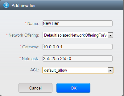
Si vous avez déjà créé un segment, le diagramme du VPC est affiché. Cliquez sur Créer un segment pour en ajouter un nouveau.
Spécifier les informations suivantes :
Tous les champs sont obligatoires.
Nom : Un nom unique pour le segment que vous créez.
Offre réseau : Les offres par défaut de réseaux sont listées : Internal LB, DefaultIsolatedNetworkOfferingForVpcNetworksNoLB, DefaultIsolatedNetworkOfferingForVpcNetworks
Dans un VPC, un seul segment peut être créé en utilisant une offre réseau avec répartition de charge activée.
Passerelle : La passerelle pour le segment que vous créez. S’assurer que la passerelle est inclue dans l’intervalle du Super CIDR que vous avez spécifié lors de la création du VPC et qu’elle n’est pas en conflit avec un segment du VPC.
VLAN : L’ID du VLAN pour le segment que l’administrateur root créé.
Cette option n’est seulement visible que si l’offre réseau que vous avez sélectionné est VLAN-enabled.
Pour plus d’informations, voir “Assigner des VLANs à des réseaux isolés”.
Masque de sous-réseau : Le masque de sous-réseau pour le segment que vous créez.
Par exemple, si le CIDR du VPC est 10.0.0.0/16 et que le réseau CIDR du tiers est 10.0.1.0/24, la passerelle du tiers est 10.0.1.1, et le masque de sous réseau du tiers est 255.255.255.0.
Cliquez sur OK.
Continuer avec la configuration des contrôle d’accès pour ce segment.
Configurer une liste de contrôle d’accès réseau
Définissez la liste de contrôle d’accès réseau (ACL) sur le routeur virtuel VPC pour contrôler le trafic entrant (ingress) et sortant (egress) entre les VPC des segments, les segments et Internet. Par défaut, tout le trafic entrant vers les réseaux invités est bloqué et tout le trafic sortant des réseaux invités est autorisé, une fois que vous ajoutez une règle ACL pour le trafic sortant, seul le trafic sortant spécifié dans cette règle ACL est autorisé, le reste est bloqué. Pour ouvrir les ports, vous devez créer une nouvelle ACL réseau. Les ACL réseau ne peuvent être créées pour les segments que si le service NetworkACL est pris en charge.
A propos des listes d’ACL réseau
Dans la terminologie CloudStack, une ACL réseau est un groupe d’entrées d’ACL réseau. Les entrées d’ACL réseau ne sont rien d’autre que des règles numérotées qui sont évaluées dans l’ordre, en commençant par la règle numérotée la plus faible. Ces règles déterminent si le trafic est autorisé en entrée ou en sortie de n’importe quel segment associé à l’ACL réseau. Vous devez ajouter les entrées d’ACL réseau à la liste d’ACL réseau, puis associer la liste ACL réseau à un segment. L’ACL réseau est associée à un VPC et peut être affectée à plusieurs VPC de segments dans un VPC. Un segment peut être associé à une ACL réseau à tout moment. Chaque segment peut être associé à une seule ACL.
L’ACL réseau par défaut est utilisée lorsqu’aucune ACL n’est associée. Le comportement par défaut est de bloquer tout le trafic entrant et d’autoriser le trafic sortant depuis les segments. L’ACL réseau par défaut ne peut pas être supprimée ou modifiée. Le contenu de l’ACL réseau par défaut est :
Règle |
Protocole |
Type de trafic |
Action | CIDR |
|---|---|---|---|---|
| 1 | Tout |
Règles entrantes |
Refuser |
0.0.0.0/0 |
| 2 | Tout |
Règles sortantes |
Refuser |
0.0.0.0/0 |
Créer les listes d’ACL
Se connecter à l’interface de CloudStack comme administrateur ou utilisateur final.
Dans la navigation à gauche, choisissez Réseau.
Dans la vue de Sélection, choisissez VPC.
All the VPCs that you have created for the account is listed in the page.
Click the Configure button of the VPC.
For each tier, the following options are displayed:
- Internal LB
- Public LB IP
- Static NAT
Machines Virtuelles
- CIDR
The following router information is displayed:
Passerelles privées
Adresses IP publiques
- Site-to-Site VPNs
Listes d’ACL réseau
Sélectionner les listes d’ACL réseaux.
Les règles par défaut suivantes sont affichées dans la page d’ACL réseau : default_allow, default_deny.
Cliquer sur Ajouter des listes d’ACL et spécifier ce qui suit :
Nom de la liste d’ACL : Un nom pour la liste d’ACL.
Description : Une description courte de la liste d’ACL qui peut être affichée aux utilisateurs.
Créer une règle d’ACL
Se connecter à l’interface de CloudStack comme administrateur ou utilisateur final.
Dans la navigation à gauche, choisissez Réseau.
Dans la vue de Sélection, choisissez VPC.
All the VPCs that you have created for the account is listed in the page.
Click the Configure button of the VPC.
Sélectionner les listes d’ACL réseaux.
En complément aux listes d’ACL personnalisées que vous avez créés, les règles par défaut suivantes sont affichées dans la page d’ACL réseaux : default_allow, default_deny.
Sélectionner la liste d’ACL désirée.
Sélectionner l’onglet Règles de liste d’ACL.
Pour ajouter une règle d’ACL, remplir les champs suivants pour spécifier quel type de trafic réseau est autorisé dans le VPC.
Numéro de règle : L’ordre dans lequel les règles sont évaluées.
CIDR : Le CIDR agit en tant que CIDR source pour les règles Ingress et en tant que CIDR de destination pour les règles Egress. Pour accepter le trafic uniquement depuis ou vers les adresses IP d’un bloc d’adresses particulier, entrez un CIDR ou une liste séparée par des virgules de CIDR. Le CIDR est l’adresse IP de base du trafic entrant. Par exemple, 192.168.0.0/22. Pour autoriser tous les CIDR, saisissez 0.0.0.0/0.
Action : Quelle action doit être prise. Autoriser le trafic ou le bloquer.
Protocole: Le protocole réseau que les sources utilisent pour envoyer le trafic vers le segment. Les protocoles TCP et UDP sont généralement utilisés pour l’échange de données et les communications avec l’utilisateur final. Le protocole ICMP est généralement utilisé pour envoyer des messages d’erreur ou des données de surveillance du réseau. All supporte tout le trafic. La dernière option est de fournir le numéro de protocole.
- Start Port, End Port (TCP, UDP only): A range of listening ports that are the destination for the incoming traffic. If you are opening a single port, use the same number in both fields.
- Protocol Number: The protocol number associated with IPv4 or IPv6. For more information, see Protocol Numbers.
- ICMP Type, ICMP Code (ICMP only): The type of message and error code that will be sent.
- Traffic Type: The type of traffic: Incoming or outgoing.
Cliquer sur Ajouter. La règle ACL est ajouée.
Vous pouvez éditer les étiquettes assignées aux règles d’ACL et supprimer les règles d’ACL que vous avez créées. Cliquer sur le bouton approprié dans l’onglet Détails.
Créer un segment avec une liste d’ACL personnalisée.
Créer un VPC.
Créer une liste d’ACL personnalisée.
Ajouter des règles d’ACL à une liste d’ACL.
Créer un segment dans le VPC.
Sélectionner la liste d’ACL désirée lors de la création du segment.
Cliquez sur OK.
Assigner une liste d’ACL personnalisée à un segment
Créer un VPC.
Créer un segment dans le VPC.
Associer le segment avec la règle d’ACL par défaut.
Créer une liste d’ACL personnalisée.
Ajouter des règles d’ACL à une liste d’ACL.
Sélectionner le segment pour lequel vous voulez assigner l’ACL personnalisée.
Cliquer sur l’icone Remplacer la liste d’ACL.

La boîte de dialogue Remplacer la liste d’ACL est affichée.
Sélectionner la liste d’ACL désirée.
Cliquez sur OK.
Ajouter une passerelle privée à un VPC
A private gateway can be added by the root admin only. The VPC private network has 1:1 relationship with the NIC of the physical network. You can configure multiple private gateways to a single VPC. No gateways with duplicated VLAN and IP are allowed in the same data center.
Se connecter à l’interface de CloudStack comme administrateur ou utilisateur final.
Dans la navigation à gauche, choisissez Réseau.
Dans la vue de Sélection, choisissez VPC.
All the VPCs that you have created for the account is listed in the page.
Click the Configure button of the VPC to which you want to configure load balancing rules.
The VPC page is displayed where all the tiers you created are listed in a diagram.
Cliquer sur l’icône Paramètres.
Les options suivantes sont affichées.
- Internal LB
- Public LB IP
- Static NAT
Machines Virtuelles
- CIDR
The following router information is displayed:
Passerelles privées
Adresses IP publiques
- Site-to-Site VPNs
Listes d’ACL réseau
Sélectionner Passerelles privées.
La page Passerelles est affichée.
Cliquer sur Ajouter une nouvelle passerelle :
add-new-gateway-vpc.png|
Spécifier les informations suivantes :
Réseau physique : Le réseau physique que vous avez créé dans la zone.
Adresse IP : L’adresse IP associée avec la passerelle du VPC.
Passerelle : La passerelle par laquelle le trafic est routé depuis et vers le VPC.
Masque de sous-réseaux : Le masque de sous-réseaux associé avec la passerelle du VPC.
VLAN : Le VLAN associé avec la passerelle du VPC.
Source NAT : Sélectionner cette option pour activer le service de NAT source sur la passerelle privée du VPC.
Voir “Source NAT on Private Gateway”.
ACL: Controls both ingress and egress traffic on a VPC private gateway. By default, all the traffic is blocked.
Voir “ACL sur une passerelle privée”.
The new gateway appears in the list. You can repeat these steps to add more gateway for this VPC.
Source NAT on Private Gateway
You might want to deploy multiple VPCs with the same super CIDR and guest tier CIDR. Therefore, multiple guest VMs from different VPCs can have the same IPs to reach a enterprise data center through the private gateway. In such cases, a NAT service need to be configured on the private gateway to avoid IP conflicts. If Source NAT is enabled, the guest VMs in VPC reaches the enterprise network via private gateway IP address by using the NAT service.
The Source NAT service on a private gateway can be enabled while adding the private gateway. On deletion of a private gateway, source NAT rules specific to the private gateway are deleted.
To enable source NAT on existing private gateways, delete them and create afresh with source NAT.
ACL sur une passerelle privée
The traffic on the VPC private gateway is controlled by creating both ingress and egress network ACL rules. The ACLs contains both allow and deny rules. As per the rule, all the ingress traffic to the private gateway interface and all the egress traffic out from the private gateway interface are blocked.
You can change this default behaviour while creating a private gateway. Alternatively, you can do the following:
In a VPC, identify the Private Gateway you want to work with.
In the Private Gateway page, do either of the following:
- Use the Quickview. See 3.
- Use the Details tab. See 4 through .
In the Quickview of the selected Private Gateway, click Replace ACL, select the ACL rule, then click OK
Click the IP address of the Private Gateway you want to work with.
Dans l’onglet Détail, cliquer sur le bouton Remplacer les ACL.
La boîte de dialogue Remplacer la liste d’ACL est affichée.
Sélectionner la règle d’ACL puis cliquer sur OK.
Wait for few seconds. You can see that the new ACL rule is displayed in the Details page.
Creating a Static Route
CloudStack enables you to specify routing for the VPN connection you create. You can enter one or CIDR addresses to indicate which traffic is to be routed back to the gateway.
In a VPC, identify the Private Gateway you want to work with.
In the Private Gateway page, click the IP address of the Private Gateway you want to work with.
Select the Static Routes tab.
Specify the CIDR of destination network.
Cliquer sur Ajouter.
Wait for few seconds until the new route is created.
Blacklisting Routes
CloudStack enables you to block a list of routes so that they are not
assigned to any of the VPC private gateways. Specify the list of routes
that you want to blacklist in the blacklisted.routes global
parameter. Note that the parameter update affects only new static route
creations. If you block an existing static route, it remains intact and
continue functioning. You cannot add a static route if the route is
blacklisted for the zone.
Déployer des VM dans un segment
Se connecter à l’interface de CloudStack comme administrateur ou utilisateur final.
Dans la navigation à gauche, choisissez Réseau.
Dans la vue de Sélection, choisissez VPC.
All the VPCs that you have created for the account is listed in the page.
Click the Configure button of the VPC to which you want to deploy the VMs.
The VPC page is displayed where all the tiers you have created are listed.
Click Virtual Machines tab of the tier to which you want to add a VM.
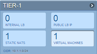
The Add Instance page is displayed.
Follow the on-screen instruction to add an instance. For information on adding an instance, see the Installation Guide.
Deploying VMs to VPC Tier and Shared Networks
CloudStack allows you deploy VMs on a VPC tier and one or more shared networks. With this feature, VMs deployed in a multi-tier application can receive monitoring services via a shared network provided by a service provider.
Se connecter à l’interface de CloudStack comme administrateur.
Dans la barre de navigation de gauche, choisir Instances.
Cliquer sur Ajouter une instance.
Sélectionner une zone.
Select a template or ISO, then follow the steps in the wizard.
Ensure that the hardware you have allows starting the selected service offering.
Under Networks, select the desired networks for the VM you are launching.
You can deploy a VM to a VPC tier and multiple shared networks.
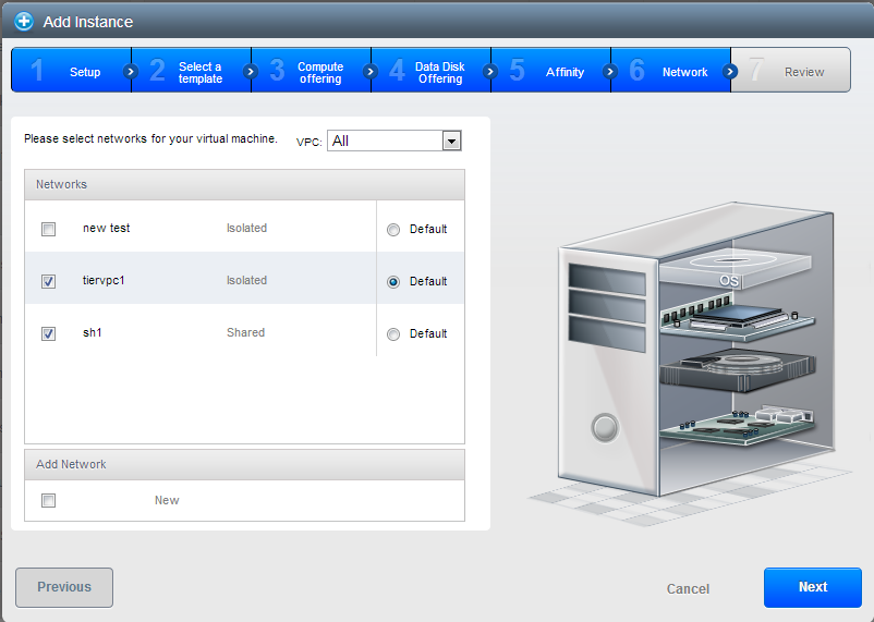
Click Next, review the configuration and click Launch.
Your VM will be deployed to the selected VPC tier and shared network.
Acquérir une nouvelle adresse IP pour un VPC
When you acquire an IP address, all IP addresses are allocated to VPC, not to the guest networks within the VPC. The IPs are associated to the guest network only when the first port-forwarding, load balancing, or Static NAT rule is created for the IP or the network. IP can’t be associated to more than one network at a time.
Se connecter à l’interface de CloudStack comme administrateur ou utilisateur final.
Dans la navigation à gauche, choisissez Réseau.
Dans la vue de Sélection, choisissez VPC.
All the VPCs that you have created for the account is listed in the page.
Click the Configure button of the VPC to which you want to deploy the VMs.
The VPC page is displayed where all the tiers you created are listed in a diagram.
Les options suivantes sont affichées.
- Internal LB
- Public LB IP
- Static NAT
Machines Virtuelles
- CIDR
The following router information is displayed:
Passerelles privées
Adresses IP publiques
- Site-to-Site VPNs
Listes d’ACL réseau
Sélectionner les adresses IP.
La page des Adresses IP Publiques est affichée.
Cliquez sur Obtenir une nouvelle adresse IP, et cliquez sur Oui dans la boîte de dialogue de confirmation.
You are prompted for confirmation because, typically, IP addresses are a limited resource. Within a few moments, the new IP address should appear with the state Allocated. You can now use the IP address in port forwarding, load balancing, and static NAT rules.
Releasing an IP Address Alloted to a VPC
The IP address is a limited resource. If you no longer need a particular IP, you can disassociate it from its VPC and return it to the pool of available addresses. An IP address can be released from its tier, only when all the networking ( port forwarding, load balancing, or StaticNAT ) rules are removed for this IP address. The released IP address will still belongs to the same VPC.
Se connecter à l’interface de CloudStack comme administrateur ou utilisateur final.
Dans la navigation à gauche, choisissez Réseau.
Dans la vue de Sélection, choisissez VPC.
All the VPCs that you have created for the account is listed in the page.
Click the Configure button of the VPC whose IP you want to release.
The VPC page is displayed where all the tiers you created are listed in a diagram.
Les options suivantes sont affichées.
- Internal LB
- Public LB IP
- Static NAT
Machines Virtuelles
- CIDR
The following router information is displayed:
Passerelles privées
Adresses IP publiques
- Site-to-Site VPNs
Listes d’ACL réseau
Sélectionner Adresses IP Publiques.
The IP Addresses page is displayed.
Cliquer sur l’IP que vous voulez rendre.
In the Details tab, click the Release IP button
Enabling or Disabling Static NAT on a VPC
A static NAT rule maps a public IP address to the private IP address of a VM in a VPC to allow Internet traffic to it. This section tells how to enable or disable static NAT for a particular IP address in a VPC.
Si les règles de redirection de port sont déjà mise en oeuvre pour une adresse IP, vous ne pouvez pas activer le static NAT pour cette IP.
Si une VM invitée fait partie de plus d’un réseau, les règles de static NAT ne fonctionneront uniquement si elle sont définies sur le réseau par défaut.
Se connecter à l’interface de CloudStack comme administrateur ou utilisateur final.
Dans la navigation à gauche, choisissez Réseau.
Dans la vue de Sélection, choisissez VPC.
All the VPCs that you have created for the account is listed in the page.
Click the Configure button of the VPC to which you want to deploy the VMs.
The VPC page is displayed where all the tiers you created are listed in a diagram.
For each tier, the following options are displayed.
- Internal LB
- Public LB IP
- Static NAT
Machines Virtuelles
- CIDR
The following router information is displayed:
Passerelles privées
Adresses IP publiques
- Site-to-Site VPNs
Listes d’ACL réseau
In the Router node, select Public IP Addresses.
The IP Addresses page is displayed.
Cliquer sur l’IP avec laquelle vous voulez travailler.
In the Details tab,click the Static NAT button.
The button toggles between Enable and
Disable, depending on whether static NAT is currently enabled for the
IP address.If you are enabling static NAT, a dialog appears as follows:
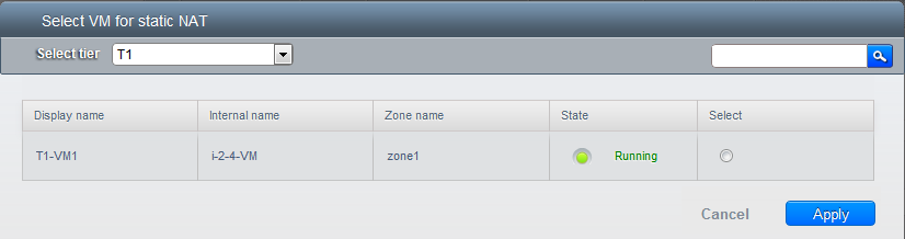
Select the tier and the destination VM, then click Apply.
Adding Load Balancing Rules on a VPC
In a VPC, you can configure two types of load balancing: external LB and internal LB. External LB is nothing but a LB rule created to redirect the traffic received at a public IP of the VPC virtual router. The traffic is load balanced within a tier based on your configuration. Citrix NetScaler and VPC virtual router are supported for external LB. When you use internal LB service, traffic received at a tier is load balanced across different VMs within that tier. For example, traffic reached at Web tier is redirected to another VM in that tier. External load balancing devices are not supported for internal LB. The service is provided by a internal LB VM configured on the target tier.
Load Balancing Within a Tier (External LB)
A CloudStack user or administrator may create load balancing rules that balance traffic received at a public IP to one or more VMs that belong to a network tier that provides load balancing service in a VPC. A user creates a rule, specifies an algorithm, and assigns the rule to a set of VMs within a tier.
Enabling NetScaler as the LB Provider on a VPC Tier
Add and enable Netscaler VPX in dedicated mode.
Netscaler can be used in a VPC environment only if it is in dedicated mode.
Create a network offering, as given in “Creating a Network Offering for External LB”.
Create a VPC with Netscaler as the Public LB provider.
For more information, see “Adding a Virtual Private Cloud”.
For the VPC, acquire an IP.
Create an external load balancing rule and apply, as given in Creating an External LB Rule.
Creating a Network Offering for External LB
To have external LB support on VPC, create a network offering as follows:
- Log in to the CloudStack UI as a user or admin.
- From the Select Offering drop-down, choose Network Offering.
Cliquer sur Ajouter une offre de réseau.
- In the dialog, make the following choices:
- Name: Any desired name for the network offering.
- Description: A short description of the offering that can be displayed to users.
- Network Rate: Allowed data transfer rate in MB per second.
- Traffic Type: The type of network traffic that will be carried on the network.
- Guest Type: Choose whether the guest network is isolated or shared.
- Persistent: Indicate whether the guest network is persistent or not. The network that you can provision without having to deploy a VM on it is termed persistent network.
- VPC: This option indicate whether the guest network is Virtual Private Cloud-enabled. A Virtual Private Cloud (VPC) is a private, isolated part of CloudStack. A VPC can have its own virtual network topology that resembles a traditional physical network. For more information on VPCs, see “About Virtual Private Clouds”.
- Specify VLAN: (Isolated guest networks only) Indicate whether a VLAN should be specified when this offering is used.
- Supported Services: Select Load Balancer. Use Netscaler or VpcVirtualRouter.
- Load Balancer Type: Select Public LB from the drop-down.
- LB Isolation: Select Dedicated if Netscaler is used as the external LB provider.
- System Offering: Choose the system service offering that you want virtual routers to use in this network.
- Conserve mode: Indicate whether to use conserve mode. In this mode, network resources are allocated only when the first virtual machine starts in the network.
- Click OK and the network offering is created.
Creating an External LB Rule
Se connecter à l’interface de CloudStack comme administrateur ou utilisateur final.
Dans la navigation à gauche, choisissez Réseau.
Dans la vue de Sélection, choisissez VPC.
All the VPCs that you have created for the account is listed in the page.
Click the Configure button of the VPC, for which you want to configure load balancing rules.
The VPC page is displayed where all the tiers you created listed in a diagram.
For each tier, the following options are displayed:
- Internal LB
- Public LB IP
- Static NAT
Machines Virtuelles
- CIDR
The following router information is displayed:
Passerelles privées
Adresses IP publiques
- Site-to-Site VPNs
Listes d’ACL réseau
In the Router node, select Public IP Addresses.
The IP Addresses page is displayed.
Click the IP address for which you want to create the rule, then click the Configuration tab.
In the Load Balancing node of the diagram, click View All.
Select the tier to which you want to apply the rule.
Spécifier les informations suivantes :
- Name: A name for the load balancer rule.
- Public Port: The port that receives the incoming traffic to be balanced.
- Private Port: The port that the VMs will use to receive the traffic.
- Algorithm. Choose the load balancing algorithm you want
CloudStack to use. CloudStack supports the following well-known
algorithms:
- Round-robin
Le moins de connexions
- Source
- Stickiness. (Optional) Click Configure and choose the algorithm for the stickiness policy. See Sticky Session Policies for Load Balancer Rules.
- Add VMs: Click Add VMs, then select two or more VMs that will divide the load of incoming traffic, and click Apply.
The new load balancing rule appears in the list. You can repeat these steps to add more load balancing rules for this IP address.
Load Balancing Across Tiers
CloudStack supports sharing workload across different tiers within your VPC. Assume that multiple tiers are set up in your environment, such as Web tier and Application tier. Traffic to each tier is balanced on the VPC virtual router on the public side, as explained in “Adding Load Balancing Rules on a VPC”. If you want the traffic coming from the Web tier to the Application tier to be balanced, use the internal load balancing feature offered by CloudStack.
How Does Internal LB Work in VPC?
In this figure, a public LB rule is created for the public IP 72.52.125.10 with public port 80 and private port 81. The LB rule, created on the VPC virtual router, is applied on the traffic coming from the Internet to the VMs on the Web tier. On the Application tier two internal load balancing rules are created. An internal LB rule for the guest IP 10.10.10.4 with load balancer port 23 and instance port 25 is configured on the VM, InternalLBVM1. Another internal LB rule for the guest IP 10.10.10.4 with load balancer port 45 and instance port 46 is configured on the VM, InternalLBVM1. Another internal LB rule for the guest IP 10.10.10.6, with load balancer port 23 and instance port 25 is configured on the VM, InternalLBVM2.
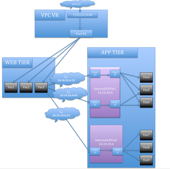
Lignes directrices
- Internal LB and Public LB are mutually exclusive on a tier. If the tier has LB on the public side, then it can’t have the Internal LB.
- Internal LB is supported just on VPC networks in CloudStack 4.2 release.
- Only Internal LB VM can act as the Internal LB provider in CloudStack 4.2 release.
- Network upgrade is not supported from the network offering with Internal LB to the network offering with Public LB.
- Multiple tiers can have internal LB support in a VPC.
- Only one tier can have Public LB support in a VPC.
Enabling Internal LB on a VPC Tier
- Create a network offering, as given in Creating a Network Offering for Internal LB.
- Create an internal load balancing rule and apply, as given in Creating an Internal LB Rule.
Creating a Network Offering for Internal LB
To have internal LB support on VPC, either use the default offering, DefaultIsolatedNetworkOfferingForVpcNetworksWithInternalLB, or create a network offering as follows:
- Log in to the CloudStack UI as a user or admin.
- From the Select Offering drop-down, choose Network Offering.
Cliquer sur Ajouter une offre de réseau.
- In the dialog, make the following choices:
- Name: Any desired name for the network offering.
- Description: A short description of the offering that can be displayed to users.
- Network Rate: Allowed data transfer rate in MB per second.
- Traffic Type: The type of network traffic that will be carried on the network.
- Guest Type: Choose whether the guest network is isolated or shared.
- Persistent: Indicate whether the guest network is persistent or not. The network that you can provision without having to deploy a VM on it is termed persistent network.
- VPC: This option indicate whether the guest network is Virtual Private Cloud-enabled. A Virtual Private Cloud (VPC) is a private, isolated part of CloudStack. A VPC can have its own virtual network topology that resembles a traditional physical network. For more information on VPCs, see “About Virtual Private Clouds”.
- Specify VLAN: (Isolated guest networks only) Indicate whether a VLAN should be specified when this offering is used.
- Supported Services: Select Load Balancer. Select
InternalLbVMfrom the provider list. - Load Balancer Type: Select Internal LB from the drop-down.
- System Offering: Choose the system service offering that you want virtual routers to use in this network.
- Conserve mode: Indicate whether to use conserve mode. In this mode, network resources are allocated only when the first virtual machine starts in the network.
- Click OK and the network offering is created.
Creating an Internal LB Rule
When you create the Internal LB rule and applies to a VM, an Internal LB VM, which is responsible for load balancing, is created.
You can view the created Internal LB VM in the Instances page if you navigate to Infrastructure > Zones > <zone_ name> > <physical_network_name> > Network Service Providers > Internal LB VM. You can manage the Internal LB VMs as and when required from the location.
Se connecter à l’interface de CloudStack comme administrateur ou utilisateur final.
Dans la navigation à gauche, choisissez Réseau.
Dans la vue de Sélection, choisissez VPC.
All the VPCs that you have created for the account is listed in the page.
Locate the VPC for which you want to configure internal LB, then click Configure.
The VPC page is displayed where all the tiers you created listed in a diagram.
Locate the Tier for which you want to configure an internal LB rule, click Internal LB.
In the Internal LB page, click Add Internal LB.
Dans la boîte de dialogue, spécifiez ce qui suit :
Name: A name for the load balancer rule.
Description: A short description of the rule that can be displayed to users.
Source IP Address: (Optional) The source IP from which traffic originates. The IP is acquired from the CIDR of that particular tier on which you want to create the Internal LB rule. If not specified, the IP address is automatically allocated from the network CIDR.
For every Source IP, a new Internal LB VM is created for load balancing.
Source Port: The port associated with the source IP. Traffic on this port is load balanced.
Instance Port: The port of the internal LB VM.
Algorithm. Choose the load balancing algorithm you want CloudStack to use. CloudStack supports the following well-known algorithms:
- Round-robin
Le moins de connexions
- Source
Adding a Port Forwarding Rule on a VPC
Se connecter à l’interface de CloudStack comme administrateur ou utilisateur final.
Dans la navigation à gauche, choisissez Réseau.
Dans la vue de Sélection, choisissez VPC.
All the VPCs that you have created for the account is listed in the page.
Click the Configure button of the VPC to which you want to deploy the VMs.
The VPC page is displayed where all the tiers you created are listed in a diagram.
For each tier, the following options are displayed:
- Internal LB
- Public LB IP
- Static NAT
Machines Virtuelles
- CIDR
The following router information is displayed:
Passerelles privées
Adresses IP publiques
- Site-to-Site VPNs
Listes d’ACL réseau
In the Router node, select Public IP Addresses.
The IP Addresses page is displayed.
Click the IP address for which you want to create the rule, then click the Configuration tab.
In the Port Forwarding node of the diagram, click View All.
Select the tier to which you want to apply the rule.
Spécifier les informations suivantes :
Public Port: The port to which public traffic will be addressed on the IP address you acquired in the previous step.
Private Port: The port on which the instance is listening for forwarded public traffic.
Protocol: The communication protocol in use between the two ports.
- TCP
- UDP
Add VM: Click Add VM. Select the name of the instance to which this rule applies, and click Apply.
You can test the rule by opening an SSH session to the instance.
Retirer des segments
You can remove a tier from a VPC. A removed tier cannot be revoked. When a tier is removed, only the resources of the tier are expunged. All the network rules (port forwarding, load balancing and staticNAT) and the IP addresses associated to the tier are removed. The IP address still be belonging to the same VPC.
Se connecter à l’interface de CloudStack comme administrateur ou utilisateur final.
Dans la navigation à gauche, choisissez Réseau.
Dans la vue de Sélection, choisissez VPC.
Tous les VPC que vous avez créé sur ce compte sont listés dans cette page.
Cliquez sur le bouton Configurer du VPC pour lequel vous désirez configurer un segment.
The Configure VPC page is displayed. Locate the tier you want to work with.
Choisir le segment que vous voulez supprimer.
In the Network Details tab, click the Delete Network button.

Click Yes to confirm. Wait for some time for the tier to be removed.
Editing, Restarting, and Removing a Virtual Private Cloud
Note
Ensure that all the tiers are removed before you remove a VPC.
Se connecter à l’interface de CloudStack comme administrateur ou utilisateur final.
Dans la navigation à gauche, choisissez Réseau.
Dans la vue de Sélection, choisissez VPC.
All the VPCs that you have created for the account is listed in the page.
Select the VPC you want to work with.
In the Details tab, click the Remove VPC button

You can remove the VPC by also using the remove button in the Quick View.
You can edit the name and description of a VPC. To do that, select the VPC, then click the Edit button.
Pour redémarrer un VPC, sélectionner le VPC puis cliquer sur le bouton Redémarrer.

Réseaux persistants
Un réseau que vous pouvez provisionner sans avoir à déployer une quelconque VM est appelé réseau persistant. Un réseau persistant peut faire partie d’un environnement VPC ou non-VPC.
Lorsque vous créez d’autres types de réseau, un réseau n’est qu’une entrée de base de données jusqu’à ce que la première VM soit créée sur ce réseau. Lors de la création de la première VM, un ID de VLAN est attribué et le réseau est provisionné. En outre, lorsque la dernière VM est détruite, l’ID du VLAN est libéré et le réseau n’est plus disponible. Avec l’ajout d’un réseau persistant, vous aurez la possibilité de créer un réseau dans CloudStack dans lequel les périphériques physiques peuvent être déployés sans avoir à exécuter une quelconque machine virtuelle. En outre, vous pouvez déployer des périphériques physiques sur ce réseau.
L’un des avantages d’avoir un réseau persistant est de pouvoir créer un VPC avec un segment composé uniquement de périphériques physiques. Par exemple, vous pouvez créer un VPC pour une application à trois tiers, déployer des VM pour le couche Web et Application et utiliser des machines physiques pour la couche Base de données. Un autre cas d’utilisation est que si vous fournissez des services en utilisant du matériel physique, vous pouvez définir le réseau comme persistant et donc même si toutes ses machines virtuelles sont détruites, ses services ne seront pas interrompus.
Considérations sur le Réseau Persistant
Le réseau persistant est conçu pour les réseaux isolés.
Toutes les offres de réseau par défaut sont non-persistantes.
Une offre de réseau ne peut pas être éditable parce la changer affectent le fonctionnement des réseaux existants qui ont été créés en utilisant cette offre de service.
Lorsque vous créez un réseau invité, l’offre de réseau que vous sélectionnez définie la persistance du réseau. Cela dépend en fait si la persistance du réseau est activée dans l’offre de réseau sélectionnée.
Un réseau existant peut devenir persistant en changeant son offre de réseau pour une offre qui a l’option de persistance activée. Lorsque cette propriété est configurée, même si le réseau n’a pas de VM en fonctionnement, le réseau est provisionné.
Un réseau existant peut devenir non-persistent en changeant son offre de réseau pour une offre qui a l’option de persistance désactivée. SI le réseau n’a pas de VM en fonctionnement durant le prochain lancement du garbage collector, il sera stoppé.
Lorsque la dernière VM d’un réseau est détruite, le garbage collector du réseau vérifie si l’offre de réseau associée avec le réseau est persistante et arrête ce réseau seulement si c’est non-persistant.
Créer un réseau invité Persistant.
Pour créer un réseau persistant, suivre les instructions suivantes :
Créer une offre réseau avec l’option Persistant activée.
Sélectionnez le réseau depuis le panneau de navigation à gauche.
Sélectionnez le réseau invité avec lequel vous voulez offrir ce service réseau.
Cliquer sur le bouton Editer.
Dans la liste de sélection Offre Réseau, sélectionnez l’offre de réseau persistant que vous venez à l’instant de créer.
Cliquez sur OK.
Setup a Palo Alto Networks Firewall
Functionality Provided
This implementation enables the orchestration of a Palo Alto Networks Firewall from within CloudStack UI and API.
The following features are supported:
- List/Add/Delete Palo Alto Networks service provider
- List/Add/Delete Palo Alto Networks network service offering
- List/Add/Delete Palo Alto Networks network using the above service offering
- Add an instance to a Palo Alto Networks network
- Source NAT management on network create and delete
- List/Add/Delete Ingress Firewall rule
- List/Add/Delete Egress Firewall rule (both ‘Allow’ and ‘Deny’ default rules supported)
- List/Add/Delete Port Forwarding rule
- List/Add/Delete Static NAT rule
- Apply a Threat Profile to all firewall rules (more details in the Additional Features section)
- Apply a Log Forwarding profile to all firewall rules (more details in the Additional Features section)
Initial Palo Alto Networks Firewall Configuration
Anatomy of the Palo Alto Networks Firewall
- In ‘Network > Interfaces’ there is a list of physical interfaces as well as aggregated physical interfaces which are used for managing traffic in and out of the Palo Alto Networks Firewall device.
- In ‘Network > Zones’ there is a list of the different configuration zones. This implementation will use two zones; a public (defaults to ‘untrust’) and private (defaults to ‘trust’) zone.
- In ‘Network > Virtual Routers’ there is a list of VRs which handle traffic routing for the Palo Alto Firewall. We only use a single Virtual Router on the firewall and it is used to handle all the routing to the next network hop.
- In ‘Objects > Security Profile Groups’ there is a list of profiles which can be applied to firewall rules. These profiles are used to better understand the types of traffic that is flowing through your network. Configured when you add the firewall provider to CloudStack.
- In ‘Objects > Log Forwarding’ there is a list of profiles which can be applied to firewall rules. These profiles are used to better track the logs generated by the firewall. Configured when you add the firewall provider to CloudStack.
- In ‘Policies > Security’ there is a list of firewall rules that are currently configured. You will not need to modify this section because it will be completely automated by CloudStack, but you can review the firewall rules which have been created here.
- In ‘Policies > NAT’ there is a list of the different NAT rules. You will not need to modify this section because it will be completely automated by CloudStack, but you can review the different NAT rules that have been created here. Source NAT, Static NAT and Destination NAT (Port Forwarding) rules will show up in this list.
Configure the Public / Private Zones on the firewall
No manual configuration is required to setup these zones because CloudStack will configure them automatically when you add the Palo Alto Networks firewall device to CloudStack as a service provider. This implementation depends on two zones, one for the public side and one for the private side of the firewall.
- The public zone (defaults to ‘untrust’) will contain all of the public interfaces and public IPs.
- The private zone (defaults to ‘trust’) will contain all of the private interfaces and guest network gateways.
The NAT and firewall rules will be configured between these zones.
Configure the Public / Private Interfaces on the firewall
This implementation supports standard physical interfaces as well as grouped physical interfaces called aggregated interfaces. Both standard interfaces and aggregated interfaces are treated the same, so they can be used interchangeably. For this document, we will assume that we are using ‘ethernet1/1’ as the public interface and ‘ethernet1/2’ as the private interface. If aggregated interfaces where used, you would use something like ‘ae1’ and ‘ae2’ as the interfaces.
This implementation requires that the ‘Interface Type’ be set to ‘Layer3’ for both the public and private interfaces. If you want to be able to use the ‘Untagged’ VLAN tag for public traffic in CloudStack, you will need to enable support for it in the public ‘ethernet1/1’ interface (details below).
Steps to configure the Public Interface:
- Log into Palo Alto Networks Firewall
- Navigate to ‘Network > Interfaces’
- Click on ‘ethernet1/1’ (for aggregated ethernet, it will probably be called ‘ae1’)
- Select ‘Layer3’ from the ‘Interface Type’ list
- Click ‘Advanced’
- Check the ‘Untagged Subinterface’ check-box
Cliquez sur ‘OK’.
Steps to configure the Private Interface:
- Click on ‘ethernet1/2’ (for aggregated ethernet, it will probably be called ‘ae2’)
- Select ‘Layer3’ from the ‘Interface Type’ list
Cliquez sur ‘OK’.
Configure a Virtual Router on the firewall
The Virtual Router on the Palo Alto Networks Firewall is not to be confused with the Virtual Routers that CloudStack provisions. For this implementation, the Virtual Router on the Palo Alto Networks Firewall will ONLY handle the upstream routing from the Firewall to the next hop.
Steps to configure the Virtual Router:
- Log into Palo Alto Networks Firewall
- Navigate to ‘Network > Virtual Routers’
- Select the ‘default’ Virtual Router or Add a new Virtual Router if there
are none in the list
- If you added a new Virtual Router, you will need to give it a ‘Name’
- Navigate to ‘Static Routes > IPv4’
- ‘Add’ a new static route
- Name: next_hop (you can name it anything you want)
- Destination: 0.0.0.0/0 (send all traffic to this route)
- Interface: ethernet1/1 (or whatever you set your public interface as)
- Next Hop: (specify the gateway IP for the next hop in your network)
Cliquez sur ‘OK’.
Cliquez sur ‘OK’.
Configure the default Public Subinterface
The current implementation of the Palo Alto Networks firewall integration uses CIDRs in the form of ‘w.x.y.z/32’ for the public IP addresses that CloudStack provisions. Because no broadcast or gateway IPs are in this single IP range, there is no way for the firewall to route the traffic for these IPs. To route the traffic for these IPs, we create a single subinterface on the public interface with an IP and a CIDR which encapsulates the CloudStack public IP range. This IP will need to be inside the subnet defined by the CloudStack public range netmask, but outside the CloudStack public IP range. The CIDR should reflect the same subnet defined by the CloudStack public range netmask. The name of the subinterface is determined by the VLAN configured for the public range in CloudStack.
To clarify this concept, we will use the following example.
Example CloudStack Public Range Configuration:
- Gateway: 172.30.0.1
- Netmask: 255.255.255.0
- IP Range: 172.30.0.100 - 172.30.0.199
- VLAN: Untagged
Configure the Public Subinterface:
- Log into Palo Alto Networks Firewall
- Navigate to ‘Network > Interfaces’
- Select the ‘ethernet1/1’ line (not clicking on the name)
- Click ‘Add Subinterface’ at the bottom of the window
- Enter ‘Interface Name’: ‘ethernet1/1’ . ‘9999’
- 9999 is used if the CloudStack public range VLAN is ‘Untagged’
- If the CloudStack public range VLAN is tagged (eg: 333), then the name will reflect that tag
- The ‘Tag’ is the VLAN tag that the traffic is sent to the next hop with, so set it accordingly. If you are passing ‘Untagged’ traffic from CloudStack to your next hop, leave it blank. If you want to pass tagged traffic from CloudStack, specify the tag.
- Select ‘default’ from the ‘Config > Virtual Router’ drop-down (assuming that is what your virtual router is called)
- Click the ‘IPv4’ tab
- Select ‘Static’ from the ‘Type’ radio options
- Click ‘Add’ in the ‘IP’ section
- Enter ‘172.30.0.254/24’ in the new line
- The IP can be any IP outside the CloudStack public IP range, but inside the CloudStack public range netmask (it can NOT be the gateway IP)
- The subnet defined by the CIDR should match the CloudStack public range netmask
Cliquez sur ‘OK’.
Commit configuration on the Palo Alto Networks Firewall
In order for all the changes we just made to take effect, we need to commit the changes.
- Click the ‘Commit’ link in the top right corner of the window
- Click ‘OK’ in the commit window overlay
- Click ‘Close’ to the resulting commit status window after the commit finishes
Setup the Palo Alto Networks Firewall in CloudStack
Add the Palo Alto Networks Firewall as a Service Provider
- Navigate to ‘Infrastructure > Zones > ZONE_NAME > Physical Network > NETWORK_NAME (guest) > Configure; Network Service Providers’
- Click on ‘Palo Alto’ in the list
Cliquer sur ‘Voir les périphériques’
- Click ‘Add Palo Alto Device’
- Enter your configuration in the overlay. This example will reflect the
details previously used in this guide.
- IP Address: (the IP of the Palo Alto Networks Firewall)
- Username: (the admin username for the firewall)
- Password: (the admin password for the firewall)
- Type: Palo Alto Firewall
- Public Interface: ethernet1/1 (use what you setup earlier as the public interface if it is different from my examples)
- Private Interface: ethernet1/2 (use what you setup earlier as the private interface if it is different from my examples)
- Number of Retries: 2 (the default is fine)
- Timeout: 300 (the default is fine)
- Public Network: untrust (this is the public zone on the firewall and did not need to be configured)
- Private Network: trust (this is the private zone on the firewall and did not need to be configured)
- Virtual Router: default (this is the name of the Virtual Router we setup on the firewall)
- Palo Alto Threat Profile: (not required. name of the ‘Security Profile Groups’ to apply. more details in the ‘Additional Features’ section)
- Palo Alto Log Profile: (not required. name of the ‘Log Forwarding’ profile to apply. more details in the ‘Additional Features’ section)
- Capacity: (not required)
- Dedicated: (not required)
Cliquez sur ‘OK’.
- Click on ‘Palo Alto’ in the breadcrumbs to go back one screen.
- Click on ‘Enable Provider’
Add a Network Service Offering to use the new Provider
There are 6 ‘Supported Services’ that need to be configured in the network service offering for this functionality. They are DHCP, DNS, Firewall, Source NAT, Static NAT and Port Forwarding. For the other settings, there are probably additional configurations which will work, but I will just document a common case.
- Navigate to ‘Service Offerings’
- In the drop-down at the top, select ‘Network Offerings’
- Click ‘Add Network Offering’
- Name: (name it whatever you want)
- Description: (again, can be whatever you want)
- Guest Type: Isolated
- Supported Services:
- DHCP: Provided by ‘VirtualRouter’
- DNS: Provided by ‘VirtualRouter’
- Firewall: Provided by ‘PaloAlto’
- Source NAT: Provided by ‘PaloAlto’
- Static NAT: Provided by ‘PaloAlto’
- Port Forwarding: Provided by ‘PaloAlto’
- System Offering for Router: System Offering For Software Router
- Supported Source NAT Type: Per account (this is the only supported option)
- Default egress policy: (both ‘Allow’ and ‘Deny’ are supported)
Cliquez sur ‘OK’.
- Click on the newly created service offering
- Click ‘Enable network offering’
When adding networks in CloudStack, select this network offering to use the Palo Alto Networks firewall.
Fonctionnalités complémentaires
In addition to the standard functionality exposed by CloudStack, we have added a couple additional features to this implementation. We did not add any new screens to CloudStack, but we have added a couple fields to the ‘Add Palo Alto Service Provider’ screen which will add functionality globally for the device.
Palo Alto Networks Threat Profile
This feature allows you to specify a ‘Security Profile Group’ to be applied to all of the firewall rules which are created on the Palo Alto Networks firewall device.
To create a ‘Security Profile Group’ on the Palo Alto Networks firewall, do the following:
- Log into the Palo Alto Networks firewall
- Navigate to ‘Objects > Security Profile Groups’
- Click ‘Add’ at the bottom of the page to add a new group
- Give the group a Name and specify the profiles you would like to include in the group
Cliquez sur ‘OK’.
- Click the ‘Commit’ link in the top right of the screen and follow the on screen instructions
Once you have created a profile, you can reference it by Name in the ‘Palo Alto Threat Profile’ field in the ‘Add the Palo Alto Networks Firewall as a Service Provider’ step.
Palo Alto Networks Log Forwarding Profile
This feature allows you to specify a ‘Log Forwarding’ profile to better manage where the firewall logs are sent to. This is helpful for keeping track of issues that can arise on the firewall.
To create a ‘Log Forwarding’ profile on the Palo Alto Networks Firewall, do the following:
- Log into the Palo Alto Networks firewall
- Navigate to ‘Objects > Log Forwarding’
- Click ‘Add’ at the bottom of the page to add a new profile
- Give the profile a Name and specify the details you want for the traffic and threat settings
Cliquez sur ‘OK’.
- Click the ‘Commit’ link in the top right of the screen and follow the on screen instructions
Once you have created a profile, you can reference it by Name in the ‘Palo Alto Log Profile’ field in the ‘Add the Palo Alto Networks Firewall as a Service Provider’ step.
Limitations
- The implementation currently only supports a single public IP range in CloudStack
- Usage tracking is not yet implemented